The following figures show the mechanical view and the dimensions of the switches.
Figure 2-1. Product View–PD-IES008x-DCxx–Angle
1
Figure 2-2. Product View–PD-IES008x-DCxx–Angle
2
Figure 2-3. Product View–PD-IES008x-DCxx–Front and Back View
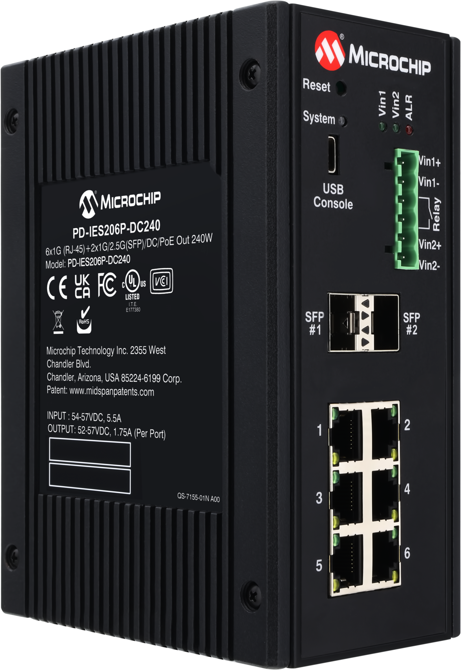
Figure 2-4. Product View–PD-IES206x-DCxx–Angle 1
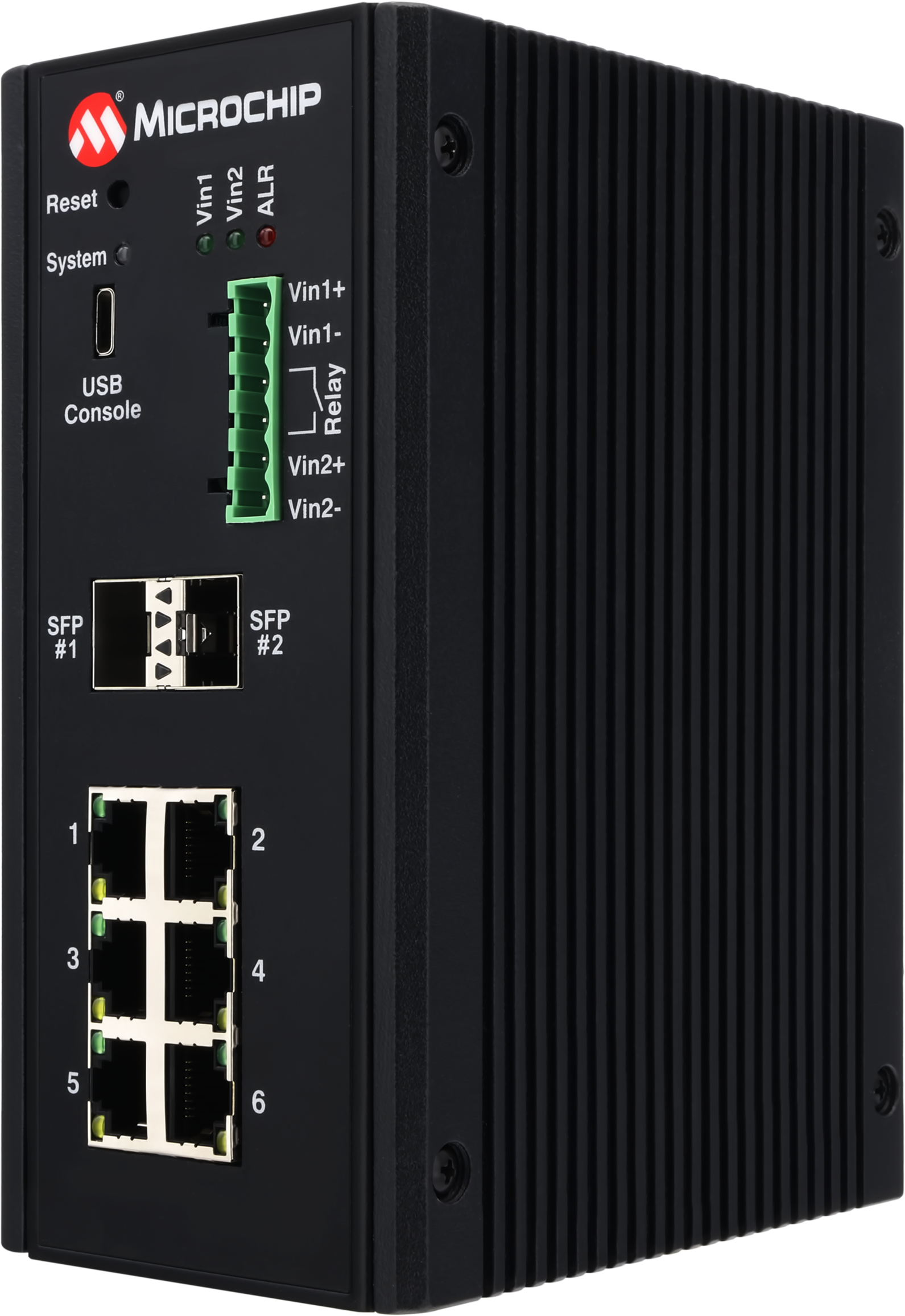
Figure 2-5. Product View–PD-IES206x-DCxx–Angle 2
Figure 2-6. Product View–PD-IES206x-DCxx–Front and Back View
Figure 2-7. Product View–PD-IES008-AC-Angle 1
Figure 2-8. Product View–PD-IES008-AC-Angle 2
Figure 2-9. Product View–PD-IES008-AC-Front and Back View
Figure 2-10. Product View–PD-IES206-AC-Angle
1
Figure 2-11. Product View–PD-IES206-AC-Angle
2
Figure 2-12. Product View–PD-IES206-AC-Front
and Back View
The following figure details the dimensions of the switch.
Figure 2-13. Product
Dimensions–PD-IES-xyy
The online versions of the documents are provided as a courtesy. Verify all content and data in the device’s PDF documentation found on the device product page.