
3.4.12 Tamper and System Signal Connectors
Unused MPU signals and PIOs are routed to separate connectors, J73 and J74. System signals are also accessible externally through these connectors.
The SAMA7G54 Curiosity Pro board provides two tamper pins for static or dynamic intrusion detection on header J73. The audio clock, shutdown and JTAGSEL signals are also available on the same connector.
Additional unused and available system signals are available on header J74.
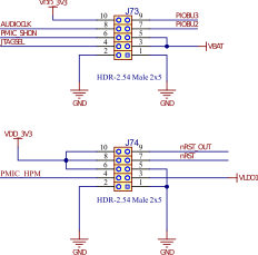
The tables below provide signal descriptions for headers J73 and J74.
Signal Name | Signal Description |
|---|---|
PIOBU2 | Tamper I/O 2 |
PIOBU3 | Tamper I/O 3 |
AUDIOCLK | Dedicated audio clock signal |
PMIC_SHDN | Signal used to enable and disable an external power supply circuit |
JTAGSEL | When pulled high, enables the JTAG boundary scan |
Signal Name | Signal Description |
|---|---|
PMIC_HPM | PMIC High-Power mode enable |
nRST_OUT | Peripheral reset output |
nRST | Processor reset input |