
3.4.7 3x CAN Interfaces
The Controller Area Network (MCAN) facilitates communication compliant with the ISO 11898-1:2015 standard and the Bosch CAN FD specification. Additional transceiver hardware is required to connect to the physical layer.
All message handling functions are implemented by the Rx Handler and the Tx Handler. The Rx Handler manages message acceptance filtering, the transfer of received messages from the CAN core to the Message RAM, and provides receive message status information. The Tx Handler is responsible for transfering transmit messages from the Message RAM to the CAN core and providing transmit status information.
Acceptance filtering is implemented using up to 128 filter elements, each of which can be configured as a range filter, bit mask filter, or dedicated ID filter.
The SAMA7G54 Curiosity Pro features three dedicated MCAN interfaces, each equipped with an MCP2542FD CAN transceiver. The MCP2542FD CAN transceiver is designed for high-speed CAN FD applications with communication speeds of up to 8 Mbps. The maximum propagation delay has been improved to support longer bus lengths. The device meets automotive requirements for CAN FD bit rates exceeding 2 Mbps, low quiescent current, electromagnetic compatibility (EMC) and electrostatic discharge (ESD).
For more information about the MCP2542FD device, refer to the product web page.
By default, all MCP2542FD CAN transceivers are enabled and can be manually placed into Standby mode by placing the appropriate jumpers on header J81.
Each CAN port features a 3-pin terminal block. Wires can be plugged into the terminal blocks without using a screwdriver.
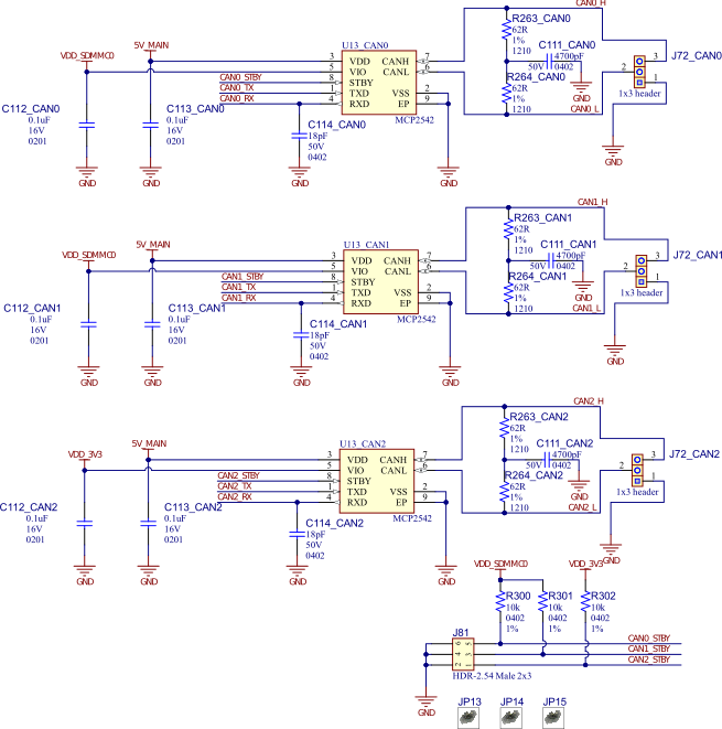
PIO | Signal Name | Signal Description |
|---|---|---|
| PA09 | CAN0_TX | CAN0 transmit signal |
PA10 | CAN0_RX | CAN0 receive signal |
| PA07 | CAN1_TX | CAN1 transmit signal |
PA08 | CAN1_RX | CAN1 receive signal |
| PD16 | CAN2_TX | CAN2 transmit signal |
PD17 | CAN2_RX | CAN2 receive signal |