1.23 TC Capture Mode
This example shows how to use the TC module in Capture mode to measure duty cycle and frequency of an external input.
Description
The TC channel is configured in Capture mode to measure duty cycle and frequency of the PWM signal. The PWM signal is generated using another TC channel which is configured in Compare mode. Output of the compare TC channel is connected to input of the capture TC channel.
Downloading and Building the Application
To clone or download this application from Github, go to the main page of this repository and then click Clone button to clone this repository or download as zip file.
Path of the application within the repository is apps/tc/tc_capture_mode.
To build the application, refer to the following table and open the project using its IDE.
| Project Name | Description |
|---|---|
|
pic32cm_pl10_curiosity_nano.X | MPLAB X project for PIC32CM PL10 Curiosity Nano Evaluation Kit |
Setting Up the Hardware
The following table shows the target hardware for the application projects.
| Project Name | Description |
|---|---|
| pic32cm_pl10_curiosity_nano.X | PIC32CM PL10 Curiosity Nano Evaluation Kit |
Setting Up PIC32CM PL10 Curiosity Nano Evaluation Kit
- TC0 generates the PWM
waveform on pin PA11
- TC0 output is routed using EIC and EVSYS to TC1 input event line
- TC1 is configured in Capture
mode
- Capture trigger is provided by input event line
- Use a jumper wire to connect pin 23 (TC0_W01) to pin 13 (EIC_EXTINT5)
- Connect the Debug USB port on the board to the computer using a USB Type-C cable
Running the Application
- Open the terminal application (e.g., Tera term) on the computer.
- Connect to the Curiosity Virtual
COM port and configure the serial settings as follows:
- Baud: 115200
- Data: 8 bits
- Parity: None
- Stop: 1 bit
- Flow Control: None
- Build and program the application using its IDE.
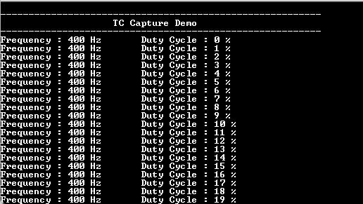
- Console displays the frequency and duty cycle of the input signal.
- Frequency is constant (400 Hz)
and duty cycle changes by 1%.