
1.1 AC Sleepwalking
This example application shows how to use the AC peripheral library to perform a comparison in Standby sleep mode periodically and wake up the device at the end of a successful comparison.
Description
In this example application compare operation is done while the CPU is in the Standby sleep mode. AC generates the interrupt on the end of the comparison which wakes the CPU.
Downloading and Building the Application
To clone or download this application from Github, go to the main page of this repository and then click Clone button to clone this repository or download as zip file.
Path of the application within the repository is apps/ac/ac_sleepwalk.
To build the application, refer to the following table and open the project using its IDE.
| Project Name | Description |
|---|---|
| pic32cm_pl10_curiosity_nano.X | MPLAB® X project for PIC32CM PL10 Curiosity Nano Evaluation Kit |
Setting Up the Hardware
The following table shows the target hardware for the application projects.
| Project Name | Board |
|---|---|
| pic32cm_pl10_curiosity_nano.X | PIC32CM PL10 Curiosity Nano Evaluation Kit |
Setting Up PIC32CM PL10 Curiosity Nano Evaluation Kit
- Connect a voltage below internal 1.024V reference to pin PA22 of the J100 header (DAC output can be fed from any external device which produce analog output, for example LabJack U3-LV)
- If using external device for analog input, connect Ground of the external device with Ground of the PIC32CM PL10 Curiosity board
- Connect the Debug USB port on the board to the computer using a USB Type-C® cable
Running the Application
- Open the terminal application (e.g., Tera term) on the computer.
- Connect to the Curiosity Virtual
COM port and configure the serial settings as follows:
- Baud: 115200
- Data: 8 bits
- Parity: None
- Stop: 1 bit
- Flow Control: None
- Build and program the application using its IDE.
- Observe output message in console
as follows:
Figure 1-1. Terminal Display 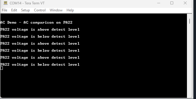
- Console displays the message stating whether voltage at AC input is lower or greater than the internal reference voltage (1.024V) generated from an internal band gap reference.
- LED toggles when comparison is done.
Refer to the following table for details of AC input pin and LED:
| Board | AC Input Pin | LED Name |
|---|---|---|
| PIC32CM PL10 Curiosity Nano Evaluation Kit | Pin 16 (PA22) of the J100 header | LED0 |