
1.2 ADC DMA Sleepwalking
This application shows how to configure the ADC in a sleepwalking operation, where the input voltage is measured at a fixed interval, and then the device is woken from sleep after conversion of 16 samples.
Description
This example application shows how to use the ADC peripheral library to perform sleepwalking and how the DMA wakes up the device after conversion of N samples. ADC conversion is triggered by RTC compare 0 event. On every trigger, input voltage is converted and the result is copied to an array in SRAM by the DMA channel. All these peripherals are operated while the CPU is in sleep. DMA generates interrupt after it transfers 16 results into the array in SRAM, which wakes the CPU.
Downloading and Building the Application
To clone or download this application from Github, go to the main page of this repository and then click Clone button to clone this repository or download as zip file.
Path of the application within the repository is apps/adc/adc_dmac_sleepwalking.
To build the application, refer to the following table and open the project using its IDE.
| Project Name | Description |
|---|---|
| pic32cm_pl10_curiosity_nano.X | MPLAB X project for PIC32CM PL10 Curiosity Nano Evaluation Kit |
Setting Up the Hardware
The following table shows the target hardware for the application projects.
| Project Name | Board |
|---|---|
| pic32cm_pl10_curiosity_nano.X | PIC32CM PL10 Curiosity Nano Evaluation Kit |
Setting Up PIC32CM PL10 Curiosity Nano Evaluation Kit
- Connect a voltage below the selected ADC reference voltage (VDDANA) to pin 50 (PA29 – ADC7_AIN9) of J100 connector (DAC output can be fed from any external device which produce analog output, for example LabJack U3-LV)
- If using external device for analog input, connect Ground of the external device with Ground of the PIC32CM PL10 Curiosity board
- Connect the Debug USB port on the board to the computer using a USB Type-C cable
Running the Application
- Open the terminal application (e.g., Tera term) on the computer.
- Connect to the Curiosity Virtual
COM port and configure the serial settings as follows:
- Baud: 115200
- Data: 8 bits
- Parity: None
- Stop: 1 bit
- Flow Control: None
- Build and program the application using its IDE.
- CPU wakes up after every 16
transfers of ADC result and updates the console as shown below:
Figure 1-2. Terminal Output 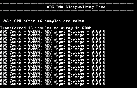
- Failure is indicated by turning ON the user LED (i.e., application failed if the LED is turned ON).
Refer to the following table for details of LED:
| Board | LED Name |
|---|---|
| PIC32CM PL10 Curiosity Nano Evaluation Kit | LED0 |