1.3 ADC Sample
This example application shows how to sample an analog input using the ADC and displays the converted samples on a serial terminal.
Description
In this application, DAC output is fed to an analog input for the ADC conversion. An analog input is converted by a software trigger and the converted value is displayed on the console. DAC output can be fed from any external device which produce analog output, for example LabJack U3-LV.
| Board | DAC Output Range |
|---|---|
| PIC32CM PL10 Curiosity Nano Evaluation Kit | 0V to 3.3V |
Downloading and Building the Application
To clone or download this application from Github, go to the main page of this repository and then click Clone button to clone this repository or download as zip file.
Path of the application within the repository is apps/adc/adc_sample.
To build the application, refer to the following table and open the project using its IDE.
| Project Name | Description |
|---|---|
| pic32cm_pl10_curiosity_nano.X | MPLAB X project for PIC32CM PL10 Curiosity Nano Evaluation Kit |
Setting Up the Hardware
The following table shows the target hardware for the application projects.
| Project Name | Board |
|---|---|
| pic32cm_pl10_curiosity_nano.X | PIC32CM PL10 Curiosity Nano Evaluation Kit |
Setting Up PIC32CM PL10 Curiosity Nano Evaluation Kit
- Analog input (AIN29) is fed
from the DAC output:
- Analog input (AIN29) is mapped to PORT pin PA29 that is routed to pin 50 of the J100 connector
- DAC output should be connected to pin 50 of the J100 connector (DAC output can be fed from any external device which produce analog output, for example LabJack U3-LV)
- If using external device for analog input, connect Ground of the external device with Ground of the PIC32CM PL10 Curiosity board
- Connect the Debug USB port on the board to the computer using a USB Type-C cable
Running the Application
- Open the terminal application (e.g., Tera term) on the computer.
- Connect to the Curiosity Virtual
COM port and configure the serial settings as follows:
- Baud: 115200
- Data: 8 bits
- Parity: None
- Stop: 1 bit
- Flow Control: None
- Build and program the application using its IDE.
- Change the DAC value between 0.0V to 3.3V.
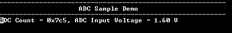
- Console displays the ADC count
and the ADC input voltage as shown below:
Figure 1-3. Terminal Display