
1.15 RSTC Reset Cause
This example shows how to use the RSTC peripheral to indicate the cause of the device reset.
Description
Reset Controller collects the various reset sources and generates reset for the device and allows the reset source to be identified by the software.
Power On Reset: Device contains a Power-On Reset (POR) detector, which keeps the system reset until power is stable. This eliminates the need for external reset circuitry to guarantee stable operation when powering up the device.
VDDANA Brown Out Reset: BOD33 resets the device if the voltage on the VDDANA pin falls below a value configured by the SYSCTRL.
LOCKUP Software Reset Flag: Its a software generates a system reset.
High Voltage Reset Flag: This bit indicates that a high-voltage event on the Reset pin triggered a system reset. When this happens, the external reset flag is set, due to a high-voltage reset is treated as a type of external reset. This helps users diagnose issues by showing that something occurred on the Reset pin, such as noise or interference.
High Voltage Present Flag: This flag indicates that a high voltage is currently detected on the Reset pin. If this bit is set, it means the device is seeing an active high-voltage condition on that pin.
Downloading and Building the Application
To clone or download this application from Github, go to the main page of this repository and then click Clone button to clone this repository or download as zip file.
Path of the application within the repository is apps/rstc/rstc_reset_cause.
To build the application, refer to the following table and open the project using its IDE.
| Project Name | Description |
|---|---|
| pic32cm_pl10_curiosity_nano.X | MPLAB X project for PIC32CM PL10 Curiosity Nano Evaluation Kit |
Setting Up the Hardware
The following table shows the target hardware for the application projects.
| Project Name | Board |
|---|---|
| pic32cm_pl10_curiosity_nano.X | PIC32CM PL10 Curiosity Nano Evaluation Kit |
Setting Up PIC32CM PL10 Curiosity Nano Evaluation Kit
- Connect the Debug USB port on the board to the computer using a USB Type-C cable
Running the Application
- Open the terminal application (e.g., Tera term) on the computer.
- Connect to the Curiosity Virtual
COM port and configure the serial settings as follows:
- Baud: 115200
- Data: 8 bits
- Parity: None
- Stop: 1 bit
- Flow Control: None
- Build and program the application using its IDE.
- LED is blinked continuously using the SysTick.
- Console displays the following
message:
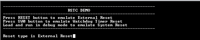
- WDT is fed periodically using SysTick to prevent the WDT reset and the LED is toggled.
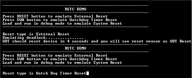
- Press the switch to put the system in deadlock (the LED should stop blinking).
- WDT will reset the device in four seconds and the demonstration should restart.
- Console displays the following
message:
Refer to the following table for details of Switch and LED:
| Board | Switch Name | LED Name |
|---|---|---|
| PIC32CM PL10 Curiosity Nano Evaluation Kit | SW0 | LED0 |