
9.7 XCVR View
(Ask a Question)The XCVR View allows the user to make assignments for Transceiver Lanes, Reference Clocks and Transmit PLLs. It presents the following views:
- A schematic view of the Reference Clock (REFCLK), the TransmitPLL, and the Transceiver Lanes they drive. See Figure 1.
- A graphical placement view of the REFCLK, its connection from the PADS, to the TransmitPLL, to the Transceiver Lanes. See Figure 2.
- A Signal Integrity View for a Transceiver Lane, showing TX Emphasis
Amplitude, TX Impedance, TX Transmit Common Mode Adjustment, RX and TX Polarity, RX
Insertion Loss, RX CTLE, RX Termination, RX P/N Board Connection, and RX Loss of Signal
Detector (Low and High). See Figure 3.
Figure 9-12. XCVR Interface—Schematic View 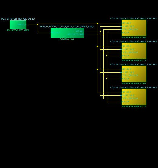
Figure 9-13. XCVR Interface—Graphical Placement View 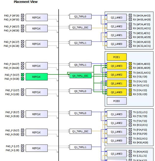
Figure 9-14. I/O Editor—XCVR View—Signal Integrity View 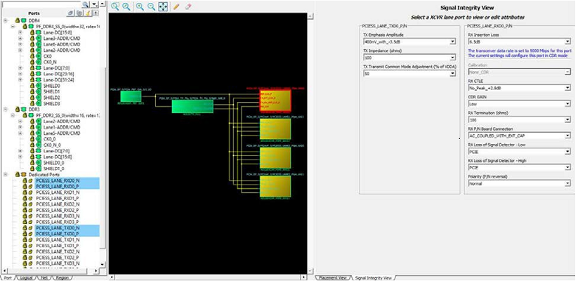
The Signal Integrity View for a Transceiver Lane shows the following:
- TX Emphasis Amplitude
- TX Impedance
- TX Transmit Common Mode Adjustment
- RX and TX Polarity, RX Insertion Loss, RX CTLE
- RX Termination
- RX P/N Board Connection
- RX Loss of Signal Detector (Low, High, Calibration, and CDR Gain)