
20.2.2.3.3 Peripherals
(Ask a Question)Select the following I/Os using the Peripherals tab:
- GPIOs from Bank 2 and Bank 4, which are dedicated to the MSS.
- Fabric I/Os, if the dedicated I/Os from Bank 2 and Bank 4 are not available.
- GPIOs from Bank 5 are dedicated to SGMII but can be routed to GMII or MII fabric I/Os. GPIO from Bank 5 are displayed only when Gigabit Ethernet MAC_0 or Gigabit Ethernet MAC_1 is selected.

By default, all peripherals are marked as Unused. To include peripherals that are required in the design, select the peripheral from the left-hand side of the window and use the corresponding drop-down to assign MSS I/Os or fabric I/Os.
The I/Os associated with the following peripherals are dedicated and cannot be assigned to fabric I/Os:
- USB peripherals are dedicated in Bank 2.
- eMMC peripherals are dedicated in Bank 4.
- Ports SD_POW and SD_WP can be disabled when not in use and can be used for other interfaces.
- SD/SDIO peripherals are dedicated in Bank 4.
The GPIOs in Bank 2 and Bank 4 have the following options:
- Unused
- MSS I/Os Bank2/4
- Static High
- Static Low
- Static High and Static Low can only be set when eMMC and SD muxing is enabled.
- GPIO_2 (Fabric) does not support Static High and Static Low options.
According to the options selected, the affected GPIOs are highlighted in green, as shown in the following figure.

I/O placement errors were detected in Peripherals Tab.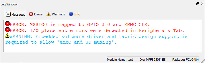
You can choose to enable either eMMC or SD at power-up using the eMMC and SD muxing option. The highlighted green-colored ports denote which I/O setting is active, whereas the orange-colored ports indicate which I/O setting is inactive.
The following warning message is generated in the log window, when the eMMC or SD setting is enabled.
Embedded software driver and fabric design support is required to allow 'eMMC and SD muxing'.The eMMC and SD cannot be used simultaneously, as shown in the following figure.
