
2.4.1.2 Configure the ADC
For the application presented in this document, the ADC will be configured in Differential mode. To configure the initial settings of the module using MCC, the user must add this module to the Project Resources.
The next step is to configure the ADC module. The ADC will be running in Differential mode, and it will convert acquired samples continuously (Free-Running mode). The resolution will be 12 bits, the prescaler value will be 4, and the differential inputs will be PD3 (positive input) and PD4 (negative input).
- Enable the ADC module
- Enable the Differential mode conversion, Free-Running
- Set the result resolution to 12-bit
- Configure the ADC prescaler to obtain an ADC frequency of 500 kHz
- Configure the ADC input pins: ADC input pin 4 as negative input; ADC input pin 3 as positive input
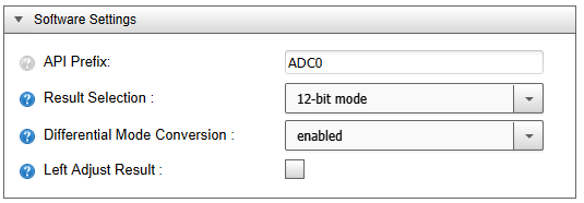
- Software Settings:
- Result Selection: 12-bit mode
- Differential Mode Conversion: enabled
- Left Adjust Result: unchecked
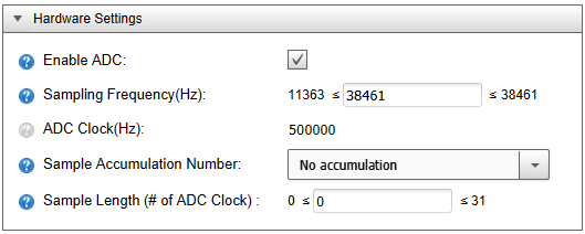
- Hardware Settings:
- Enable ADC: checked
The settings are described in Figure 2-12 and Figure 2-13.
Additionally, the user must configure the ADC registers. To know what settings are available in which register and to find the available configurations of a register’s bits and bit fields, the user must consult the device data sheet.
The Free-Running mode option is available in the Control A (CTRLA) register of the ADC module. By writing to the CTRLA register, the user can enable/disable the Running in Standby mode, select the conversion mode, set the result adjustment, select the resolution, and enable/disable the peripheral. The clock frequency for this peripheral must be configured using the Prescaler (PRESC) bit field in Control C (CTRLC) register.
To use the ADC in Differential mode, two analog inputs are needed. The positive input must be configured using the MUX Selection for Positive ADC Input (MUXPOS) register, and similarly, the negative input must be configured using the MUX Selection for Negative ADC Input (MUXNEG) register. The respective pins must also be configured as analog inputs, with digital buffers disabled.
The configuration of the registers can be done using MCC, in the Registers tab.
- Register: CTRLA
- FREERUN: enabled
Figure 2-14. ADC0 CTRLA Register 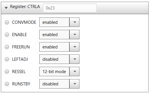
- FREERUN: enabled
- Register: CTRLC
- PRESC: CLK_PER divided by
4
Figure 2-15. ADC0 CTRLC Register 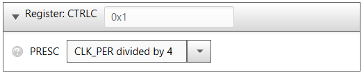
- PRESC: CLK_PER divided by
4
- Register: MUXNEG
- MUXNEG: ADC input pin 4
- Register: MUXPOS
- MUXPOS: ADC input pin 3
Figure 2-16. ADC0 MUXNEG and MUXPOS Registers 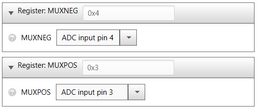
- MUXPOS: ADC input pin 3