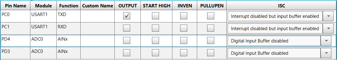
From the Pin Manager: Grid View window, the input pins for the ADC must be
selected. Select PD3 and PD4, as described in Figure 2-19. The receive and transmit
pins for USART must be configured as presented below.
Figure 2-19. Pin Manager: Grid View
To be used as ADC inputs, the input pins must be configured as analog inputs
(the digital buffers must be disabled). The weak pull-ups and the interrupts must be
disabled.
Todo: Using
MCC, do the following settings:
Disable digital input buffers on
the respective pins
Disable weak pull-up on the
respective pins
Disable interrupts
Result: Go to
Resource Management [MCC] → Project Resources → Pin Module and do
the configurations presented in Figure 2-20.Figure 2-20. Pin Module
The online versions of the documents are provided as a courtesy. Verify all content and data in the device’s PDF documentation found on the device product page.