After converting the received analog data using the ADC, the data can be sent further to
be analyzed by the user. To transmit the data to the developing computer host, the USART
peripheral module will be used. On the AVR128DA48 Curiosity Nano board, the USART1 RX
(receiving) and TX (transmitting) pins are connected directly to the debugger pins, so
the user will be able to send data to the computer without additional wires. Therefore,
the USART peripheral module used in this application will be USART1.
Todo: Add the
USART1 module to the project using MCC.
Result: Go to
Resource Management [MCC] → Device Resources → Peripherals → USART
and add the USART1 peripheral module by clicking the green + sign. The module
will appear in the Project Resources window.
After introducing the module to the project, some initial configurations must be done.
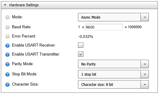
Todo: Configure
the USART1 to run in Asynchronous mode, with the baud rate of 9600, with no parity, and
with 1 stop bit. The character size must be of 8 bits.
Info: There is
no need for the USART RX to be enabled: The device does not need data from the computer.
Only the USART TX needs to be enabled.
Result: Go to
Resource Management [MCC] → Project Resources → Peripherals and
select USART1. From the Easy Setup tab, the following configurations must
be done:
The online versions of the documents are provided as a courtesy. Verify all content and data in the device’s PDF documentation found on the device product page.