4.10.2.3.3 Network Access Control List (ACL) Configuration
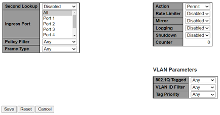
Configure an Access Control Entry (ACE) on the Access Control List Configuration page. An ACE consists of several parameters. These parameters vary according to the frame type that you select. First, select the ingress port for the ACE, and then select the frame type. Different parameter options are displayed depending on the frame type selected. A frame that hits this ACE matches the configuration that is defined here. The following figure shows the global parameters of the ACE configuration.

The Access Control List Configuration page has the following parameters:
- Global Configuration
- Second Lookup: Specify the second lookup operation of ACE
- Ingress
Port: Select the ingress port for which this ACE applies
- All: ACE applies to all ports
- Port n: ACE applies to this port number, where n is the number of the switch port
- Policy
Filter: Specify the policy number filter for this ACE
- Any: No policy filter is specified (policy filter status is don't-care)
- Specific: If you want to filter a specific policy with this ACE, then choose this value. Two fields for entering the policy value and the bitmask appear.
- Policy Value: When Specific is selected for the policy filter, then you can enter a specific policy value. The allowed range is 0 to 63.
- Policy
Bitmask: When Specific is selected
for the policy filter, then you can enter a specific policy bitmask. The
allowed range is 0x0 to 0x3f. While using bitmask, if the binary bit value
is 0, then it means this bit is
don't-care. The real matched pattern is
[policy_value and policy_bitmask]. For example, if the policy value is 3 and the policy bitmask is 0x10 (bit 0 is don't-care bit), then policies 2 and 3 are applied to this rule. - Frame
Type: Select the frame type for this ACE. These frame types
are mutually exclusive.
- Any: Any frame can match this ACE
- Ethernet Type: Only Ethernet Type frames can match this ACE. The IEEE 802.3 standard describes the value of Length/Type Field specifications to be greater than or equal to 1536 decimal (equal to 0600 hexadecimal) and the value must not be equal to 0x800 (IPv4), 0x806 (ARP), or 0x86DD (IPv6).
-
ARP: Only ARP frames can match this ACE
Note: The ARP frames do not match the ACE with ethernet type. -
IPv4: Only IPv4 frames can match this ACE
Note: The IPv4 frames do not match the ACE with ethernet type. - IPv6: Only IPv6 frames can match this
ACENote: The IPv6 frames do not match ACE with Ethernet type.
- Action: Specify the
action to take with a frame that hits this ACE
- Permit: The frame that hits this ACE is granted permission for the ACE operation
- Deny: The frame that hits this ACE is dropped
- Filter: Frames matching ACE are filtered
- Rate Limiter: Specify the rate limiter in number of base units. The allowed range is 1–16. Disabled indicates that the rate limiter operation is disabled.
- Port Redirect: Frames that hit the ACE are redirected to the port number specified here. The rate limiter affects these ports. The allowed range is the same as the switch port number range. Disabled indicates that the port redirect operation is disabled, and the specific port number of Port Redirect cannot be set when action is permitted.
- Mirror: Specify the mirror operation of this port.
Frames matching the ACE are mirrored to the destination mirror port. The
rate limiter does not affect frames on the mirror port. The allowed values
are:
-
Enabled: Frames received on the port are mirrored
-
Disabled: Frames received on the port are not mirrored
The default value is Disabled.
-
-
Logging: Specify the logging operation of ACE
Note: The logging message doesn't include the 4 bytes CRC information.The allowed values are:
- Enabled: Frames matching ACE are stored in the System Log
- Disabled: Frames matching ACE are not logged
Note: The logging feature only works when the packet length is less than 1518 (without VLAN tags) and the System Log memory size and logging rate is limited. - Shutdown: Specify the port shut down operation
of ACE. The allowed values are:
- Enabled: If a frame matches ACE, the ingress port is disabled
- Disabled: Port shutdown is disabled for ACE
Note: The shutdown feature only works when the packet length is less than 1518 (without VLAN tags). - Counter: The counter indicates the number of times ACE was hit by a frame.
- VLAN Parameters
- 802.1Q
Tagged: Specify whether frames can hit the action according
to the 802.1Q tagged. The allowed values are:
- Any: Any value is allowed (don't-care)
- Enabled: Tagged frame only
- Disabled: Untagged frame only
The default value is Any.
- VLAN ID
Filter: Specify the VLAN ID filter for this ACE.
- Any: No VLAN ID filter is specified (VLAN ID filter status is don't-care)
- Specific: If you want to filter a specific VLAN ID with this ACE, then choose this value. A field for entering a VLAN ID number appears.
- VLAN ID: When Specific is selected for the VLAN ID filter, you can enter a specific VLAN ID number. The allowed range is 1 to 4095. A frame that hits this ACE matches this VLAN ID value.
- Tag Priority: Specify the tag priority for this ACE. A frame that hits this ACE matches this tag priority. The allowed number range is 0 to 7 or range 0–1, 2–3, 4–5, 6–7, 0–3, and 4–7. The value Any means that no tag priority is specified (tag priority is don't-care).
- 802.1Q
Tagged: Specify whether frames can hit the action according
to the 802.1Q tagged. The allowed values are:
- MAC Parameters: The MAC
parameters are only displayed when the frame type is Ethernet Type or
ARP
Figure 4-43. ACE Configuration—MAC Parameters 
- SMAC
Filter: Specify the source MAC filter for this ACE
- Any: No SMAC filter is specified (SMAC filter status is don't-care)
- Specific: If you want to filter a specific source MAC address with this ACE, choose this value. A field for entering a SMAC value appears.
- SMAC
Value: When Specific is selected for
the SMAC filter, you can enter a specific source MAC address. The legal
format is
xx-xx-xx-xx-xx-xxorxx.xx.xx.xx.xx.xxorxxxxxxxxxxxx(x is a hexadecimal digit). A frame that hits this ACE matches this SMAC value. - DMAC
Filter: Specify the destination MAC filter for this ACE
- Any: No DMAC filter is specified (DMAC filter status is don't-care)
- MC: Frame must be multicast
- BC: Frame must be broadcast
- UC: Frame must be unicast
- Specific: If you want to filter a specific destination MAC address with this ACE, choose this value. A field for entering a DMAC value appears.
- DMAC
Value: When Specific is selected for
the DMAC filter, you can enter a specific destination MAC address. The legal
format is
xx-xx-xx-xx-xx-xxorxx.xx.xx.xx.xx.xxorxxxxxxxxxxxx(x is a hexadecimal digit). A frame that hits this ACE matches this DMAC value.
- SMAC
Filter: Specify the source MAC filter for this ACE
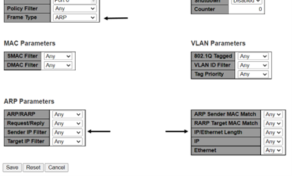
- ARP Parameters: The ARP
parameters can be configured when Frame Type ARP is selected.
The following figure shows the ARP parameters of the ACE configuration.
Figure 4-44. ACE Configuration—ARP Parameters 
- ARP/RARP: Specify the available ARP/RARP opcode
(OP) flag for this ACE.
- Any: No ARP/RARP OP flag is specified (OP is don't-care)
- ARP: Frame must have ARP opcode set to ARP
- RARP: Frame must have RARP opcode set to RARP
- Other: Frame has unknown ARP/RARP Opcode flag
- Request/Reply: Specify the available
Request/Reply opcode (OP) flag for this ACE
- Any: No Request/Reply OP flag is specified (OP is don't-care)
- Request: Frame must have ARP Request or RARP Request OP flag set
- Reply: Frame must have ARP Reply or RARP Reply OP flag
- Sender IP
Filter: Specify the sender IP filter for this ACE
- Any: No sender IP filter is specified (sender IP filter is don't-care)
- Host: Sender IP filter is set to Host. Specify the sender IP address in the SIP Address field that appears
- Network: Sender IP filter is set to Network. Specify the sender IP address and sender IP mask in the SIP Address and SIP Mask fields that appear.
- Sender IP
Address: When Host or Network is selected for the sender IP
filter, you can enter a specific sender IP address in dotted decimal
notation.Note: The invalid IP address configuration is also acceptable. For example, 0.0.0.0. Normally, an ACE with invalid IP address is explicitly add deny action.
- Sender IP Mask: When Network is selected for the sender IP filter, you can enter a specific sender IP mask in dotted decimal notation.
- Target IP
Filter: Specify the target IP filter for this specific
ACE.
- Any: No target IP filter is specified (target IP filter is don't-care)
- Host: Target IP filter is set to Host. Specify the target IP address in the Target IP Address field that appears.
- Network: Target IP filter is set to Network. Specify the target IP address and target IP mask in the Target IP Address and Target IP Mask fields that appear.
- Target IP
Address: When Host or Network is selected for the target IP
filter, you can enter a specific target IP address in dotted decimal
notation.Note: The invalid IP address configuration is also acceptable. For example, 0.0.0.0. Normally, an ACE with invalid IP address is explicitly add deny action.
- Target IP Mask: When Network is selected for the target IP filter, you can enter a specific target IP mask in dotted decimal notation
- ARP Sender MAC
Match: Specify whether frames can hit the action according
to their Sender Hardware Address (SHA) field settings
- 0: ARP frames where SHA is not equal to the SMAC address
- 1: ARP frames where SHA is equal to the SMAC address
- Any: Any value is allowed (don't-care)
- RARP Target MAC
Match: Specify whether frames can hit the action according
to their Target Hardware Address (THA) field settings
- 0: RARP frames where THA is not equal to the target MAC address
- 1: RARP frames where THA is equal to the target MAC address
- Any: Any value is allowed (don't-care)
-
IP/Ethernet Length: Specify whether frames can hit
the action according to their ARP/RARP Hardware Address Length (HLN) and
Protocol Address Length (PLN) settings.
- 0: ARP/RARP frames where the HLN is not equal to Ethernet (0x06) or the (PLN) is not equal to IPv4 (0x04)
- 1: ARP/RARP frames where the HLN is equal to Ethernet (0x06) and the (PLN) is equal to IPv4 (0x04)
- Any: Any value is allowed (don't-care)
- IP:
Specify whether frames can hit the action according to their ARP/RARP
Hardware Address Space (HRD) settings.
- 0: ARP/RARP frames where the HLD is not equal to Ethernet (1)
- 1: ARP/RARP frames where the HLD is equal to Ethernet (1)
- Any: Any value is allowed (don't-care)
- Ethernet: Specify whether frames can hit the
action according to their ARP/RARP protocol address space (PRO) settings.
- 0: ARP/RARP frames where the PRO is not equal to IP (0x800)
- 1: ARP/RARP frames where the PRO is equal to IP (0x800).
- Any: Any value is allowed (don't-care)
- ARP/RARP: Specify the available ARP/RARP opcode
(OP) flag for this ACE.
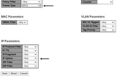
- IP Parameters: The IP
parameters can be configured when Frame Type IPv4 is
selected. The following figure shows the IP parameters of the ACE configuration.
Figure 4-45. ACE Configuration IP Parameters 
- IP Protocol Filter: Specify
the IP protocol filter for this ACE
- Any: No IP protocol filter is specified (don't-care)
- Specific: If you want to filter a specific IP protocol filter with this ACE, choose this value. A field for entering an IP protocol filter appears.
- ICMP: Select ICMP to filter IPv4 ICMP protocol frames. Extra fields for defining ICMP parameters appear. These fields are explained later in this help file.
- UDP: Select UDP to filter IPv4 UDP protocol frames. Extra fields for defining UDP parameters appear. These fields are explained later in this help file.
- TCP: Select TCP to filter IPv4 TCP protocol frames. Extra fields for defining TCP parameters appear. These fields are explained later in this help file.
- IP Protocol Value: When Specific is selected for the IP protocol value, you can enter a specific value. The allowed range is 0–255. A frame that hits this ACE matches this IP protocol value.
- IP TTL: Specify the
Time-to-Live (TLL) settings for this ACE
- zero: IPv4 frames with a TLL field greater than zero must not be able to match this entry
- non-zero: IPv4 frames with a TLL field greater than zero must be able to match this entry
- Any: Any value is allowed (don't-care)
- IP Fragment: Specify the
fragment offset settings for this ACE. This involves the settings for the More
Fragments (MF) bit and the Fragment Offset (FRAG OFFSET) field for an IPv4 frame.
- No: IPv4 frames where the MF bit is set or the FRAG OFFSET field is greater than zero must not be able to match this entry
- Yes: IPv4 frames where the MF bit is set or the FRAG OFFSET field is greater than zero must be able to match this entry
- Any: Any value is allowed (don't-care)
- IP Option: Specify the options
flag setting for this ACE
- No: IPv4 frames where the options flag is set must not be able to match this entry
- Yes: IPv4 frames where the options flag is set must be able to match this entry
- Any: Any value is allowed (don't-care)
- SIP Filter: Specify the source
IP filter for this ACE
- Any: No source IP filter is specified (source IP filter is don't-care)
- Host: Source IP filter is set to Host. Specify the source IP address in the appearing SIP Address field that appears.
- Network: Source IP filter is set to Network. Specify the source IP address and source IP mask in the SIP Address and SIP Mask fields that appear.
- SIP Address: When Host or
Network is selected for the source IP filter, you can enter a specific SIP address
in dotted decimal notationNote: The invalid IP address configuration is also acceptable. For example, 0.0.0.0. Normally, an ACE with invalid IP address is explicitly add deny action.
- SIP Mask: When Network is selected for the source IP filter, you can enter a specific SIP mask in dotted decimal notation.
- DIP Filter: Specify the
destination IP filter for this ACE.
- Any: No destination IP filter is specified (destination IP filter is don't-care)
- Host: Destination IP filter is set to Host. Specify the destination IP address in the DIP Address field that appears.
- Network: Destination IP filter is set to Network. Specify the destination IP address and destination IP mask in the DIP Address and DIP Mask fields that appear.
-
DIP Address: When Host or Network is selected for the destination IP filter, you can enter a specific DIP address in dotted decimal notation
Note: The invalid IP address configuration is also acceptable. For example, 0.0.0.0. Normally, an ACE with invalid IP address is explicitly add deny action. - DIP Mask: When Network is selected for the destination IP filter, you can enter a specific DIP mask in dotted decimal notation
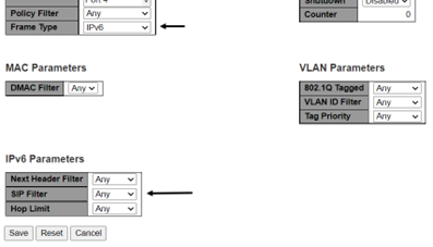
- IPv6 Parameters: The IPv6
parameters can be configured when Frame Type IPv6 is
selected. The following figure shows the IPv6 parameters of the configuration.
Figure 4-46. ACE Configuration—IPv6 Parameters 
- Next Header Filter: Specify
the IPv6 next header filter for this ACE
- Any: No IPv6 next header filter is specified (don't-care)
- Specific: If you want to filter a specific IPv6 next header filter with this ACE, choose this value. A field for entering an IPv6 next header filter appears.
- ICMP: Select ICMP to filter IPv6 ICMP protocol frames. Extra fields for defining ICMP parameters appear. These fields are explained later in this help file.
- UDP: Select UDP to filter IPv6 UDP protocol frames. Extra fields for defining UDP parameters appear. These fields are explained later in this help file.
- TCP: Select TCP to filter IPv6 TCP protocol frames. Extra fields for defining TCP parameters appear. These fields are explained later in this help file.
- Next Header Value: When Specific is selected for the IPv6 next header value, you can enter a specific value. The allowed range is 0 to 255. A frame that hits this ACE matches this IPv6 protocol value.
- SIP Filter: Specify the source
IPv6 filter for this ACE
- Any: No source IPv6 filter is specified (Source IPv6 filter is don't-care)
- Specific: Source IPv6 filter is set to Network. Specify the source IPv6 address and source IPv6 mask in the SIP Address fields that appear.
- SIP Address: When Specific is selected for the source IPv6 filter, you can enter a specific SIPv6 address. The field only supported the last 32 bits for IPv6 address.
- SIP BitMask: When
Specific is selected for the source IPv6 filter, you can
enter a specific SIPv6 mask. The field only supported the last 32 bits for IPv6
address.Note: The usage of bitmask, if the binary bit value is 0 means that this bit is don't-care. The real matched pattern is [sipv6_address and sipv6_bitmask] (last 32 bits). For example, if the SIPv6 address is 2001::3 and the SIPv6 bitmask is 0xFFFFFFFE (bit 0 is don't-care bit), then SIPv6 addresses 2001::2 and 2001::3 are applied to this rule.
- Hop Limit: Specify the hop
limit settings for this ACE
- zero: IPv6 frames with a hop limit field greater than zero must not be able to match this entry
- non-zero: IPv6 frames with a hop limit field greater than zero must be able to match this entry
- Any: Any value is allowed (don't-care)
