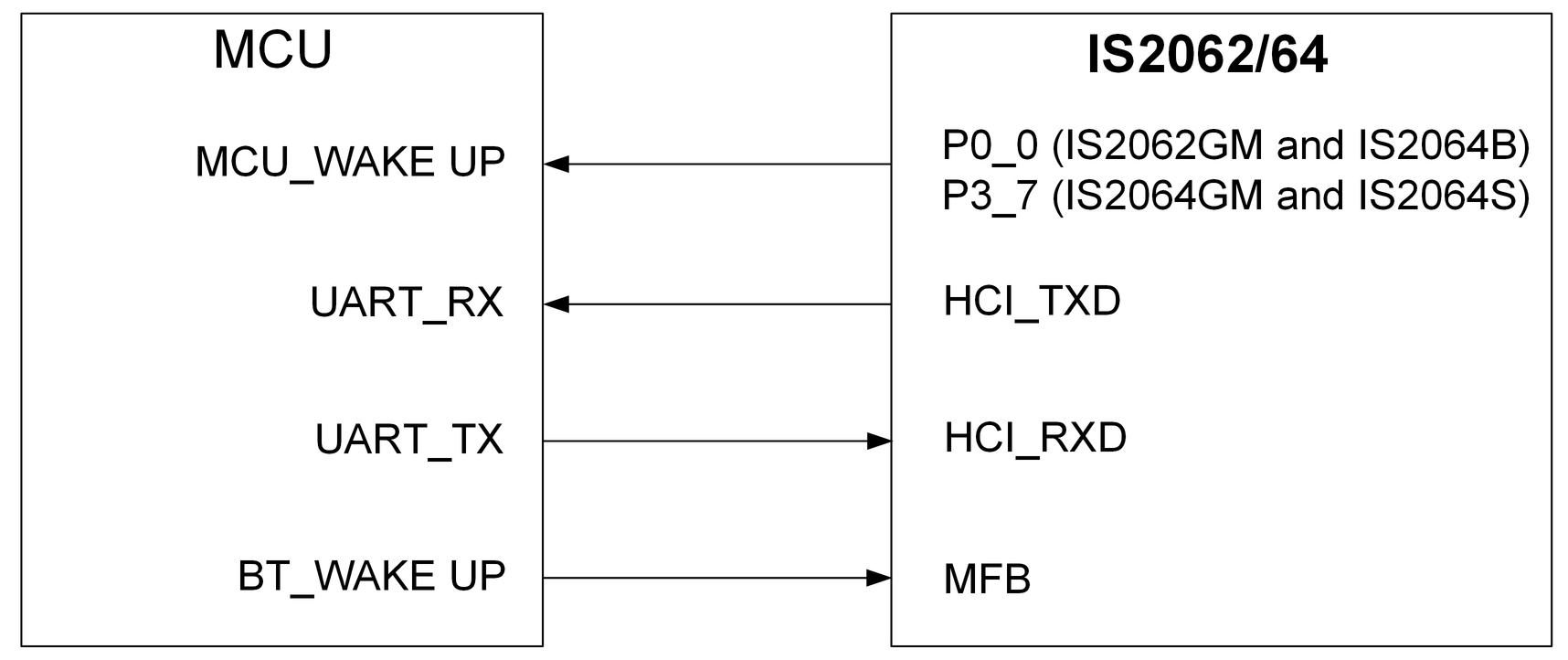
The following figure illustrates the UART interface between the IS2062/64 SoC
and an external MCU.
Figure 6-2. HOST MCU INTERFACE OVER UART
The MCU controls the IS2062/64 SoC over the UART interface and wakes up the SoC
using the MFB, P0_0 (IS2062GM and IS2064B) and P3_7 (IS2064GM and IS2064S) pins.
Refer to the "UART_CommandSet" document for a list of functions that the
IS2062/64 SoC supports and how to use the UI tool to set up the system using the UART command.
The following figures illustrate the various UART
control signal timing sequences.Figure 6-3. POWER-ON/OFF SEQUENCE
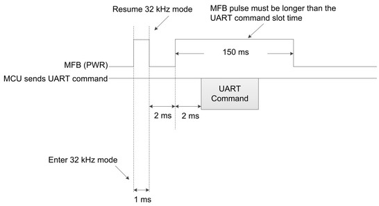
Figure 6-4. TIMING SEQUENCE OF RX INDICATION AFTER
POWER-ON
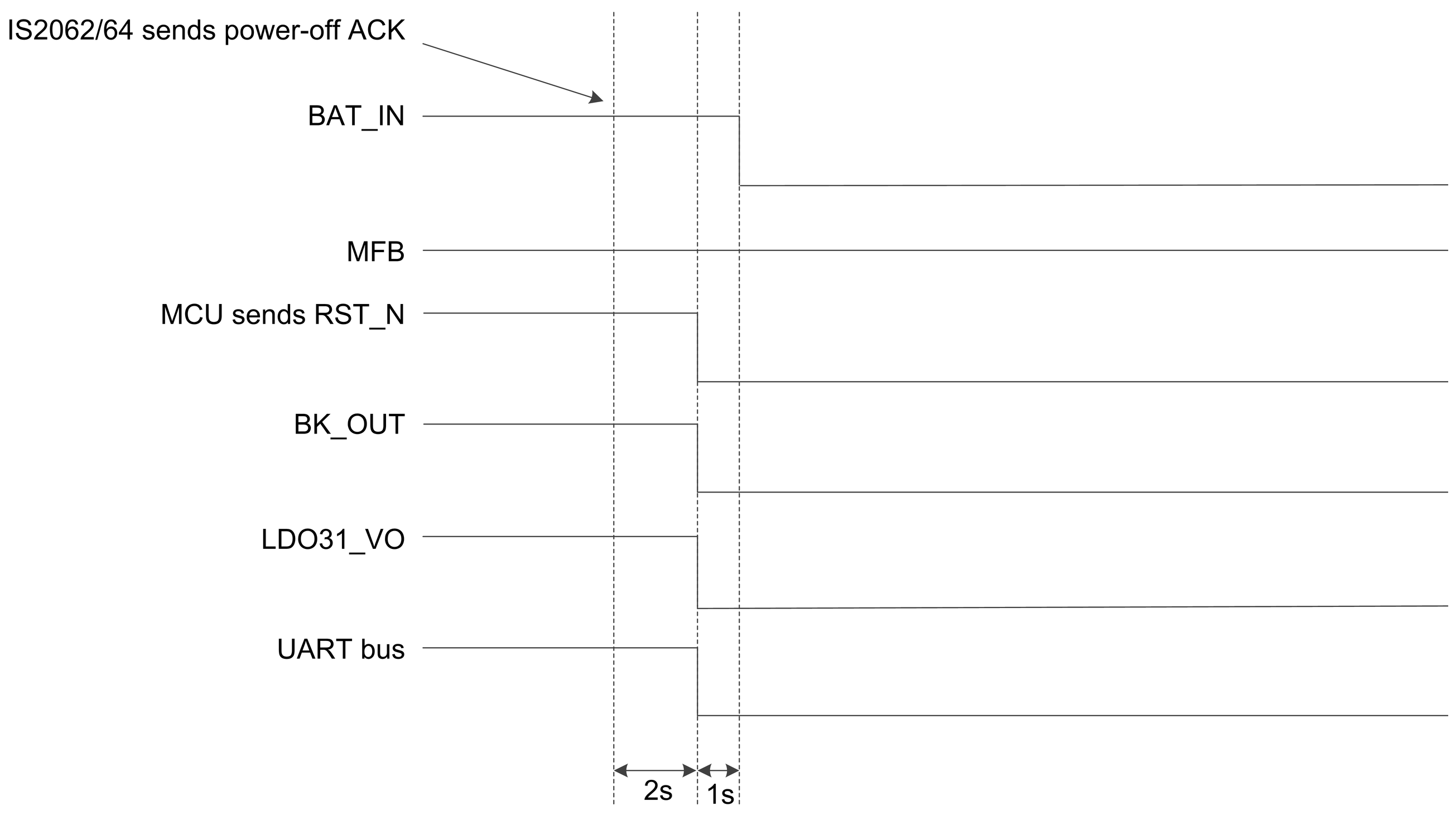
Figure 6-5. TIMING SEQUENCE OF POWER-OFF
Note:
EEPROM clock = 100 kHz.
For a byte wire, 0.01 ms x 32 clock x 2
= 640 μs.
It is recommended to have ramp-down
time more than 640 μs during the power-off sequence to ensure safe operation of the
device.
Figure 6-6. TIMING SEQUENCE OF POWER-ON
(NACK)
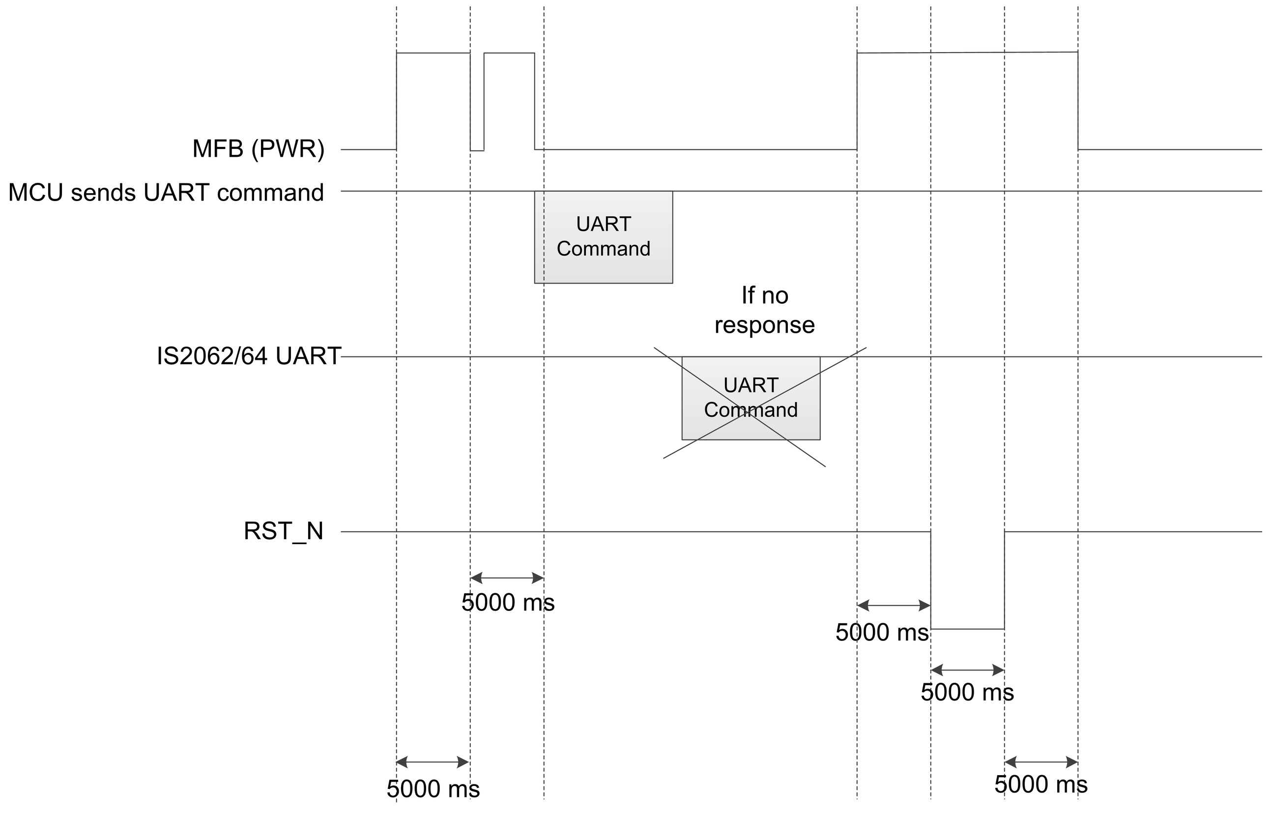
Figure 6-7. RESET TIMING SEQUENCE IN CASE OF NO
RESPONSE FROM SoC TO HOST MCU
Note: The MCU sends the UART command again,
when SoC is not responding to its first UART command. If the SoC is not responding to the
second UART command within 5 secs, then the MCU forces the system to Reset.
Figure 6-8. TIMING SEQUENCE OF POWER DROP
PROTECTION
Note:
It is recommended to connect the
battery on a BAT_IN pin of the SoC for power supply.
If an external power source or a power
adapter is utilized to provide the power to the SoC (ADAP_IN), use a voltage supervisor
IC.
The Reset IC output
pin, RST_N,
must be “Open drain”
type and threshold
voltage as
2.93V.
The RST_N signal must be fully pulled to low before BAT_IN power drop to 2.7V.
The online versions of the documents are provided as a courtesy. Verify all content and data in the device’s PDF documentation found on the device product page.