Mount the AVR128DB48 Curiosity Nano host board and the RNWF11 Add On Board on Curiosity Nano base board
at respective headers. For more details about the boards placement in the
Curiosity Nano base, refer to the Figure 6-1.
Connect the debugger USB port on
the AVR128DB48 Curiosity Nano board to computer
using a micro USB cable
Change the configuration. There
are two options to change the configuration:
Option 1: Change the
configuration manually in the code.
Open the code in
MPLAB IDE v6.00 or higher and add Home AP and device information
in the application code.
In
rnwf_app.h, add Wi-Fi
configurations in HOME_AP_SSID,
HOME_AP_PASSPHRASE,
HOME_AP_SECURITY.
In
rnwf_app.c, change
sock_port in tcp_client_sock_6666
to the port number of the running TCP server and change
sock_addr to the IP address where
the TCP server is running.
Option 2: Change the
configuration via MCC Melody.
For more details
about Wi-Fi configurations, refer Figure 3-5.
The
following fields can be configured via MCC Melody Wi-Fi
settings:
SSID
Security Type
Passphrase
Refer Figure 3-10 to understand how to make NET Configuration changes.
The
following fields can be configured via MCC Melody NET
configuration settings:
Server / Client Mode Selection – Select Client
Mode
Save the changes and then build
and program the code to the hardware using MPLAB X IDE.Figure 6-2. Programming the
Board
Open the Terminal application
(for example, Tera Term or PuTTY) on the PC
Connect to the “USB to UART” COM
port and configure the serial settings as follows:
Baud – 115200
Data – 8 Bits
Parity – None
Stop – 1 Bit
Flow Control –
None
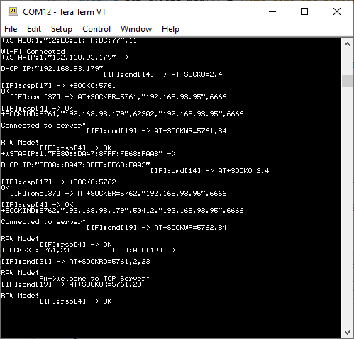
As the board boots up, it will
connect to Home-AP and print the IP address obtained. The board will establish a
connection with configured TCP Server and print a success message. Once the TCP
client-server connection is successful, the application will continue listening
on the socket for incoming messages and then write them back to the server.Figure 6-3. TCP Client Serial
Logs
Use any standard utility on the laptop (such as a python script, packet sender
or any other preferred utility) to run a TCP Server.