
22.5 Paths Tab
The Paths tab displays timing analysis information for categories of paths, known as "sets," and the paths within each set. The Paths tab displays the sets in the set spreadsheet (at top) and the paths within each set (at bottom).
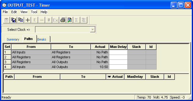
The Paths tab default setting displays four path sets:
From All Inputs To All Registers / CLK
Displays all paths from the input ports of the design to the synchronous input pins of all the registers in the current clock domain. In this instance, CLK is an example of the current clock domain.
From All Registers / CLK To All Registers / CLK
Displays all paths from the clock pin of registers in the current clock domain to the synchronous input pins of all the registers in the current clock domain; in this instance, CLK is an example of the current clock domain. To view the register setup and clock skew, right-click the desired path in the paths grid and choose Expand Path from the context menu, or click the Expand Path button.
To view the Hold time (instead of the Setup time), change your setting in the Timer Preferences, Changing and Displaying paths.
From All Registers / CLK To All Outputs
Displays all paths from the clock pin of registers in the current clock domain to the primary outputs of the design.
All Inputs To All Outputs
Displays all input ports to all output ports in the design. This set is completely asynchronous (independent of the clock).
All the sets default to display the longest path in the category. You can change this default setting by choosing Preferences from the File menu. When you select a set, Timer displays the paths within the set in the lower spreadsheet labeled "Paths." The spreadsheet displays a sorted list of paths (the number of paths it displays is controlled in the Preferences dialog box). Double-click the column headings to sort the columns.
The timing information displayed for sets and paths includes:
- Actual: The actual delay calculated by Timer for each path. Timer does not include setup time and destination register data when calculating the Actual delay.
- Max Delay: The maximum required delay specified. Do not interpret this value as the clock frequency. To set clock frequency, input on the Summary tab, or on the Clocks tab. Timer includes setup time and skew when calculating Max Delay.
- Slack: The difference between the maximum required delay and the actual delay.
- ID: The constraint ID for the path.