
5.3 Getting Started
(Ask a Question)The following sections describe how to start using Libero SoC.
5.3.1 Starting Libero SoC
(Ask a Question)- Clicking New starts the New Project Creation Wizard. Use this wizard to create new Libero SoC projects.
- Clicking Open opens an existing Libero SoC project.
5.3.2 Design Report
(Ask a Question)The Design Report tab lists the reports available for your design. Reports are added automatically as you move through design development. For example, timing reports are added when you run timing analysis on your design. Reports are updated each time you run a timing analysis.
To display the Design Report tab, click Design > Reports.
If a report is not listed in the tab, you might have to create it manually. For example, you must start Verify Power manually before its report is available.
| Category | Report |
|---|---|
| Project Summary | |
| Programming | |
| Export |
5.3.3 Creating a New Project
(Ask a Question)To simplify project creation, Libero SoC provides a wizard that takes you through the process of creating a new Libero SoC project.
| Screen | Description |
|---|---|
| Project Details | Specify the name and location of your project, device family and parts, I/O standards, and HDL source files and design constraint files. |
| Device Selection | Select a device for your project. After you select a device, or in any wizard screen that follows, you can click the Finish button to create the project and exit the wizard. |
| SmartFusion 2 and IGLOO 2: Device Settings | Specify the device I/O technology and reserve pins for probes. |
| Design Template | This dialog box might not be available if there are no design templates for the chosen technology. |
| Add HDL Sources | Add HDL design source files to your Libero SoC project. |
| Add Constraints | Add timing and physical constraints files to your Libero SoC project. |
5.3.3.1 New Project Creation Wizard: Project Details
(Ask a Question)Project Details is the first screen that appears in the New Project Creation Wizard.
The following table describes the fields in the Project Details screen. After you complete the fields, click Next to go to Device Selection.
| Field | Description |
|---|---|
| Project Name | Identifies your project name. Do not use spaces or reserved Verilog or VHDL keywords. |
| Project Location | Identifies your project location on disk. |
| Description | General information about your design and project. |
| Preferred HDL Type | Sets your HDL type to one of the following:
Libero-generated files (SmartDesigns, SmartGen cores, and so on) are created in the HDL type you specify. Libero SoC supports mixed HDL designs. |
| Enable Block Creation | Allows you to build blocks for your design. These blocks can be assembled in other designs, with partial layout, and been optimized for timing and power performance for a specific Microchip device. Once optimized, you can use the same blocks in multiple designs. |
5.3.3.2 New Project Creation Wizard: Device Selection
(Ask a Question)The Device Selection screen is where you can specify the Microchip device for your project. Use the filters and drop-down lists to refine your search for the right part to use for your design.
This screen contains a table of all the parts, with associated FPGA resource details generated based on a value you enter in a filter. When you select a filter value:
- The parts table is updated to reflect the result of the new filtered value.
- All other filters are updated, and
only relevant items are available in the filter drop-down lists. For example, if you
select PolarFire in the Family filter,
the parts table includes only PolarFire parts, and the Die
filter includes only PolarFire dies in the Die drop-down
list.
Figure 5-15. Libero SoC New Project Creation Wizard - Device Selection The following table describes the fields in the Device Selection screen. After you complete the fields, click Next to go to the Device Settings screen or click Finish to create the new project by accepting all of the remaining default settings.Table 5-11 5-16 5-17. Fields in the Libero SoC New Project Creation Wizard - Device Selection Field Description Family Microchip device family. Only devices that belong to the family appear in the parts table. Die/Package/Speed Device die, package, and speed grade. Use the Die/Package/Speed filters to view only the selections that interest you. The Die/Package/Speed grades available for selection depend on the level of Libero SoC license you have (Evaluation, Silver, Gold, or Platinum). For more information, see the Libero SoC Licensing web page. Core Voltage Core voltage for your device. Two numbers separated by a “~” are shown if a wide range voltage is supported. For example, 1.2~1.5 means that the device core voltage can vary between 1.2 and 1.5 volts. Range (PolarFire) Voltage and temperature range a device might encounter in your application. Tools such as SmartTime, SmartPower, timing-driven layout, power-driven layout, the timing report, and back-annotated simulation are affected by operating conditions. Select the appropriate option for your device. Supported operating condition ranges vary according to your device and package. To find your recommended temperature range, see your device datasheet. Choices are:
- All: All ranges
- EXT: Extended
- IND: Industrial
- MIL: Military
Range (SmartFusion 2, IGLOO 2, and RTG4) Temperature ranges a device can encounter in your application. Junction temperature is a function of ambient temperature, air flow, and power consumption. Tools such as SmartTime, SmartPower, timing-driven layout, power-driven layout, the timing report, and back-annotated simulation are affected by operating conditions. Choices are: - ALL: All ranges
- EXT: Extended
- COM: Commercial (not available for RTG4 devices)
- IND: Industrial
- TGrade1: Automotive (not available for RTG4 devices)
- TGrade2: Automotive (not available for RTG4 devices)
- MIL: Military
Supported operating condition ranges vary according to your device and package. Refer to the device datasheet to find your recommended temperature range. The temperature range corresponding to the value selected from the pick list can also be found by checking .
Reset Filters Resets all filters to the default ALL option except Family. Search Parts Character-by-character search for parts. Search results appear in the parts table.
5.3.3.3 New Project Creation Wizard: Device Settings
(Ask a Question)Device settings vary by device family.
5.3.3.3.1 PolarFire Device Settings
(Ask a Question)
| Field | Description |
|---|---|
| Core Voltage | Set the core voltage for your device. |
| Default I/O technology | Set all your I/Os to a default value. You can change the values for individual I/Os in the I/O Attribute Editor. The I/O Technology available is family-dependent. |
| Reserve pins for probes | Reserve your pins for probing if you intend to debug using SmartDebug. If unchecked, the I/Os can be used as General Purpose I/Os. |
5.3.3.3.2 SmartFusion 2 and IGLOO 2 Device Settings
(Ask a Question)
| Field | Description |
|---|---|
| Default I/O technology | Set all your I/Os to a default value. You can change the values for individual I/Os in the I/O Attribute Editor. The I/O Technology available is family-dependent. |
| Reserve pins for probes | Reserve your pins for probing if you intend to debug using SmartDebug. If unchecked, the I/Os can be used as General Purpose I/Os. |
| PLL supply voltage (V) | Set the voltage for the power supply that you plan to connect to all the PLLs in your design, such as MDDR, FDDR, SERDES, and FCCC. |
| VDD Supply Ramp Time | Power-up management circuitry is designed into every SmartFusion
2 and IGLOO 2 FPGA. These circuits ensure easy transition from the
powered-off state to the powered-up state of the device. The
SmartFusion 2, IGLOO 2, and RTG4 system controller is responsible
for systematic power-on reset whenever the device is powered on or
reset. All I/Os are held in a high-impedance state by the system
controller until all power supplies are at their required levels and
the system controller has completed the reset sequence. The power-on reset circuitry in SmartFusion 2 and IGLOO 2 devices requires the VDD and VPP supplies to ramp monotonically from 0 V to the minimum recommended operating voltage within a predefined time. There is no sequencing requirement on VDD and VPP. Four ramp rate options are available during design generation: 50 μs, 1 ms, 10 ms, and 100 ms. Each selection represents the maximum ramp rate to apply to VDD and VPP. Device information (such as Die, Package, and Speed) can be modified later in the Project Settings dialog box. |
| System controller suspended mode | Suspends operation of the System Controller. Checking this box places the System Controller in a reset state when the device is powered up. This suspends all system services from being performed. For a list of system services for SmartFusion 2 and IGLOO 2, see the System Controller User's Guide for your device. |
5.3.3.3.3 RTG4 Device Settings
(Ask a Question)
| Field | Description |
|---|---|
| Default I/O technology | Set all your I/Os to a default value. You can change the values for individual I/Os in the I/O Attribute Editor. The I/O Technology available is family-dependent. |
| Reserve pins for probes | Reserve your pins for probing if you intend to debug using SmartDebug. If unchecked, the I/Os can be used as General Purpose I/Os. |
| Enable Single Event Transient mitigation | Controls the mitigation of Single Event Transient (SET) in the FPGA fabric. When this box is checked, SET filters are turned on globally to help mitigate radiation-induced transients. By default, this box is not checked. |
5.3.3.4 New Project Creation Wizard: Design Template (SmartFusion 2 and IGLOO 2)
(Ask a Question)
The following table describes the fields in the Device Template screen. After you complete the fields, click Next to go to the Add HDL Sources page or click Finish to create the new project by accepting all of the remaining default settings.
| Field | Description |
|---|---|
| None | Select if you do not want to use a design template. |
| Create a System Builder based design | Use System Builder to generate your top-level design. |
| Create a Microcontroller (MSS) based design | Instantiate a Microcontroller (MSS) in your design. The version of the MSS cores available in your vault is displayed. Select the version you desire. |
| Use Standalone Initialization for MDDR/FDDR/SERDES Peripherals | Check if you want to create your own peripheral initialization logic in SmartDesign for each design peripheral (MDDR/FDDR/SERDES). When checked, System Builder does not build the peripherals initialization logic for you. Stand-alone initialization is useful if you want to make the initialization logic of each peripheral separate from and independent of each other. |
| Instantiate System Builder/MSS component in a SmartDesign on creation | Uncheck if you are using this project to create System Builder or MSS components and do not plan on using them in a SmartDesign based design. This is especially useful for design flows where the System Builder or MSS components are stitched in a design using HDL. |
5.3.3.5 New Project Creation Wizard: Add HDL Source Files
(Ask a Question)| Element | Description |
|---|---|
| Import File button | Imports an HDL source file. When the dialog box appears, go to
the location where the HDL source resides, select the HDL file, and
click Open. The HDL file is copied to the
<prj_folder>/hdl folder in your Libero
project. |
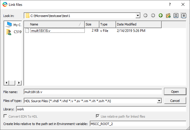
| Link File button | Allows you to continue with an absolute or relative path for linked files. When the Link files dialog box appears (see the following figure), go to the location where the HDL source resides, select the HDL file, and click Open. |
| Create links relative to the path set in Environment variable |
Available when you click the Link File button. The HDL file is linked to the Libero project. Check this check box if the HDL source file is located and maintained outside the Libero project. This option requires you to specify an environment variable that has a relative path set to it. Links are created relative to the path set in the environment variable. Note: If you select
relative path and provide an environment variable for the
relative path, you cannot switch to absolute path. After the
environment variable is set, this option becomes read-only in
all other link files dialog boxes.
|
| Delete button | Deletes the selected HDL source file from your project. If the HDL source file is linked to the Libero project, the link will be removed. |
5.3.3.6 New Project Creation Wizard: Add Constraints
(Ask a Question)| Element | Description |
|---|---|
| Import File button | Go to the location where the constraints file resides. Select the
constraints file and click Open. The
constraints file is copied to the
<prj_folder>/constraint folder in your
Libero project. |
| Link File button | Click this button if the constraint file is located and maintained outside the Libero project. When the Link files dialog box appears (see the following figure), specify an absolute path or choose a relative path for linked files. Go to the location where the constraints file resides. Select the constraints file and click Open. The constraints file is linked to the Libero project. |
| Create links relative to the path set in Environment variable |
Available when you click the Link File button. The constraints file is linked to the Libero project. Check this check box if the constraints file is located and maintained outside the Libero project. This option requires you to specify an environment variable that has a relative path set to it. Links are created relative to the path set in the environment variable. Note: If you select
relative path and provide an environment variable for the
relative path, you cannot switch to absolute path. After the
environment variable is set, this option becomes read-only in
all other link files dialog boxes.
|
| Delete button | Deletes the selected constraints file from your project. If the constraints file is linked to the Libero project, the link will be removed. |

5.3.4 Opening a Project
(Ask a Question)To open a project:
- From the File menu, choose Open Project.
- Select the project file you want to open. The file ends in the extension
.prjx. - Click Open.
- A Design Flow window appears on the left side.
- A log and message window appear at the bottom.
- Project information windows appear on the right side.
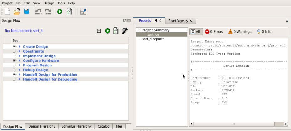
The Design Flow window might appear different for each technology family. However, all flows include some version of the following design steps:
- Create Design
- Constraints
- Implement Design
- Configure Hardware
- Program Design
- Debug Design
- Handoff Design for Production
- Handoff Design for Debugging