
1.19 PM Low-Power Features
This example highlights the power consumption for each sleep mode based on the same application integration.
Description
This example application configures RTC to generate an interrupt or event (regarding sleep mode and configuration) to start an ADC conversion from light sensor value every 1 ms. The DMAC move the converted value from ADC Result to internal SRAM and after 10 transfers, DMA generates an interrupt to wake-up core and process data through DGI SPI pins. Application initial sleep mode state is IDLE mode. Pressing the SW0 button allows to go from one sleep mode to another.
Below is the low-power configuration for this application:
- Voltage Regulator is a Buck Converter
- Low Power Efficiency Mode is enabled
- Performance Level 2 (PL2) Mode is selected
- Power Domain Switchable (PDSW) is always ACTIVE
Downloading and Building the Application
To clone or download this application from Github, go to the main page of this repository and then click Clone button to clone this repository or download as zip file. This content can also be downloaded using content manager by following these instructions.
Path of the application within the repository is apps/pm/low_power_features/firmware.
To build the application, refer to the following table and open the project using its IDE.
| Project Name | Description |
|---|---|
| pic32cm_le00_curiosity_pro.X | MPLABX project for PIC32CM LE00 Curiosity Pro Evaluation Kit |
Setting Up the Hardware
The following table shows the target hardware for the application projects.
| Project Name | Board |
|---|---|
| pic32cm_le00_curiosity_pro.X | PIC32CM LE00 Curiosity Pro Evaluation Kit |
| I/O1 Xplained Pro Extension Kit | I/O1 Xplained Pro Extension Kit |
Setting Up PIC32CM LE00 Curiosity Pro Evaluation Kit
- Plug the I/O1 Xplained Pro Extension Kit to the EXT1 header on the board
- Short pin 2 and pin 3 of J205 jumper (XAM is measuring the MCU current consumption)
- Connect the Debug USB port on the board to the computer using a micro USB cable
Running the Application
- Build and Program the application using its IDE
- Open and Configure the Microchip’s Atmel Data Visualizer
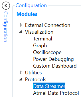
- Open a Data Streamer in
Configuration > Protocols
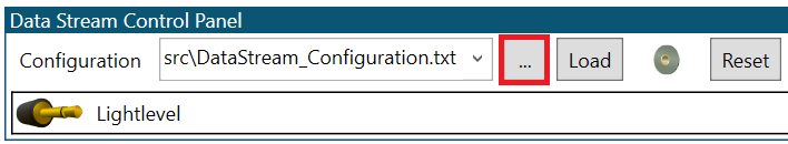
- Configure and Load the
Data Streamer with the DataStream_Configuration text file available in
apps/pm/low_power_features/firmware/src/
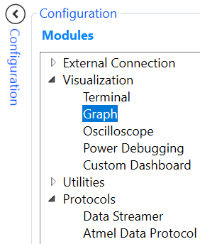
- Open a Graph in
Configuration > Visualization
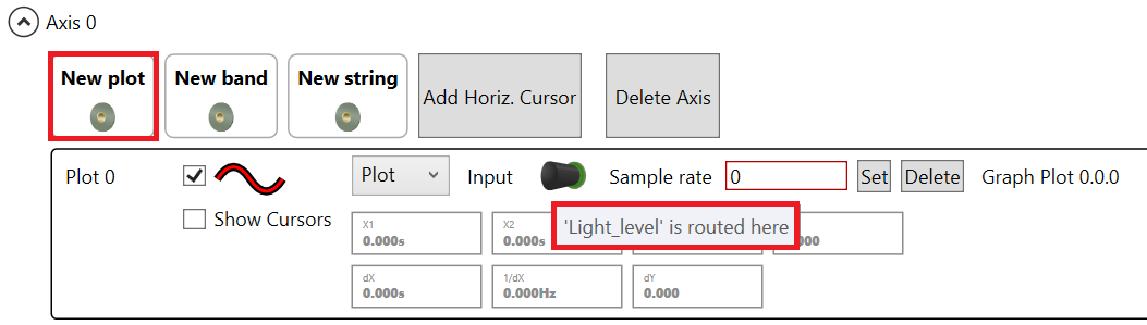
- Drag & Drop the Light
Level icon to Graph window as a New plot
- Connect the board with
DGI Control Panel
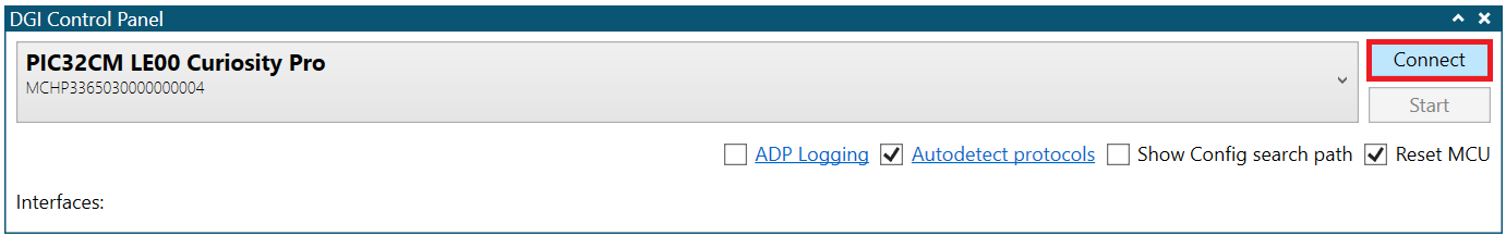
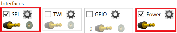
- Select SPI & Power
interfaces
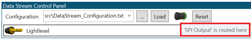
- Drag & Drop the SPI
icon to Data Stream Control Panel
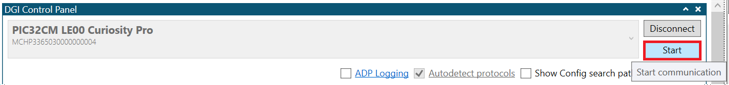
- Start the communication
with the board
- Open a Data Streamer in
Configuration > Protocols
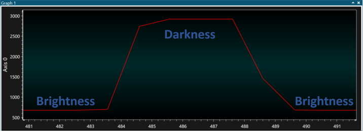
- Cover the light sensor (for
example, by placing a hand over it) of I/O1 Xplained Pro Extension Kit and then
uncover the light sensor. Observe the SPI Output as below
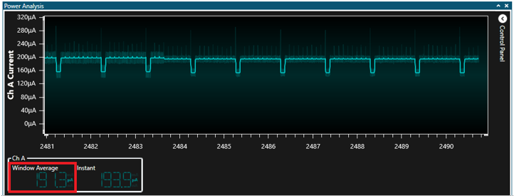
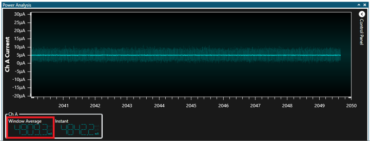
- Observe the power consumption in
IDLE mode as below
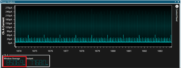
- Press SW0 button to enter STANDBY
with IRQ mode and observe the power consumption as below
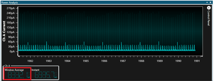
- Press SW0 button to enter STANDBY
with SleepWalking mode and observe the power consumption as below
- Press SW0 button to enter OFF
mode and observe the power consumption as below
Press RESET button when the device is in OFF mode to restart code example at initial sleep state (IDLE)