
3.4.3.1 USB Port A
On this board, the USBA port can function as either a host or a device interface. It is accessible through the USB Type-C® connector (J1).
Two resistors are placed on its power rail to form a voltage divider that converts 5V to 3.3V. This voltage is used to indicate the presence of a USB host to the MPU.
As described in the USB Supply Input section, the USBA port can also be used as a power source. In most cases, this port is limited to 500 mA.
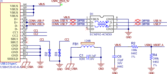
Pin No | Signal Name | Signal Description |
|---|---|---|
A4, A9, B4, B9 | USBA_VBUS_5V | USB 5V power input |
| A6, B6 | USBA_CONN_P | USB port data plus |
A7, B7 | USBA_CONN_N | USB port data minus |
A1, A12, B1, B12 | GND | Ground |
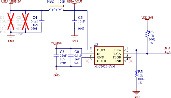
In Host mode, the USB host port A uses a 500 mA high-side power switch output from a MIC2026 device. This setup supports both self-powered and bus-powered applications. The USBIO_EN_A signal controls the MIC2026 current-limiting power switch, which supplies power to the client device. The USB specification requires that bus-powered USB 2.0 devices do not exceed a current limit of 500 mA. To comply with this requirement, the MIC2026 limits the current and indicates an overcurrent condition through the USBIO_OC_A signal. For more information about the MIC2026, refer to the product web page.
PIO | Signal Name | Signal Description |
|---|---|---|
PC6 | USBIO_VBDET_A | VBUS detection |
| - | USBIO_EN_A | USBA host power enable signal |
| - | USBIO_OC_A | USBA power overcurrent interrupt line |