
4.2.1 Connecting the Board to the Host PC PCIe Slot
(Ask a Question)- After successful programming, power OFF the PolarFire Evaluation/Splash board and shut down the host PC.
- Connect the CON3-PCIe Edge connector of the
PolarFire Evaluation/Splash board to the host PC's PCIe slot through the PCI Edge
card ribbon cable.
This demo is designed to work with any PCIe Gen2 compliant slot.
If the host PC does not support Gen2 compliant slot, the demo switches to Gen1
mode.Important:The following figure shows the board setup for the host PC in which the PolarFire Evaluation Kit is connected to the host PC PCIe slot using PCIe Edge Card Ribbon cable (not supplied with the kit).
- Power OFF the host PC while inserting the PCIe Edge connector. If it is not powered OFF, the PCIe device detection and the selection of Gen1 or Gen2 mode might fail. The device detection and selection depend on the host PC PCIe configuration.
- After connecting the board to the host PC, the host PC may power on without manually switching on the PC.
Figure 4-3. PolarFire Evaluation Kit Setup for Host PC 
- Power-on the power supply switch SW3.
The following figure shows the board setup for the host PC in which the PolarFire Splash Kit is connected to the host PC PCIe slot.

- Power-on the power supply switch SW1.
- Power-on the host PC and check the Device Manager of the Host PC for the PCIe Device. The following figure shows the example Device Manager window.
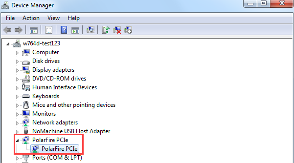
Important: If the device is still not detected, check if the BIOS version in the host PC is the latest and if PCI is enabled in the host PC BIOS.