
15.9.2 Route View
The Route view displays a representation of the routes. This feature shows the general location of routing segments used by the design.
To activate the route view in ChipPlanner:
- Complete Layout. To display routes, Layout must be completed before running ChipPlanner.
- Select the assigned macro in either the ChipPlanner window or the Physical tab of the Hierarchy window. Select multiple macros by holding down the CTRL key.
- From the Nets menu, choose Show Routes, or click the Show Routes toolbar button.
The following screen shows a route view for a ProASIC3E design followed by a route view for an Axcelerator design. Note that the module icons look different from the way they appear in the Ratsnest view. Also, notice how the routing views for Flash families differ from those for Axcelerator.
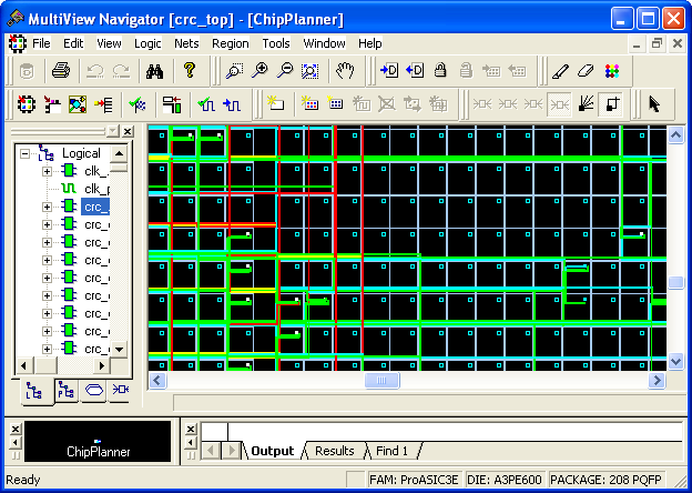
Axcelerator designs include routing buffers and "clusters." Clusters include one SEQ, two COMB, and one buffer. Routing buffers are used to redirect traffic. Axcelerator designs can include many extra routing buffers.
You can use the Display Settings dialog box to change the color schemes used in routing. The default colors are red for clocks, yellow for locked modules, and green for RAM.
To display routes for one or more nets, select at least one net form the Nets tab in the Hierarchy view window when in Route view. When you select one or more macros, the connected nets are also selected. When in Route view, you can see the routing tree for the selected nets (see screen shown above).
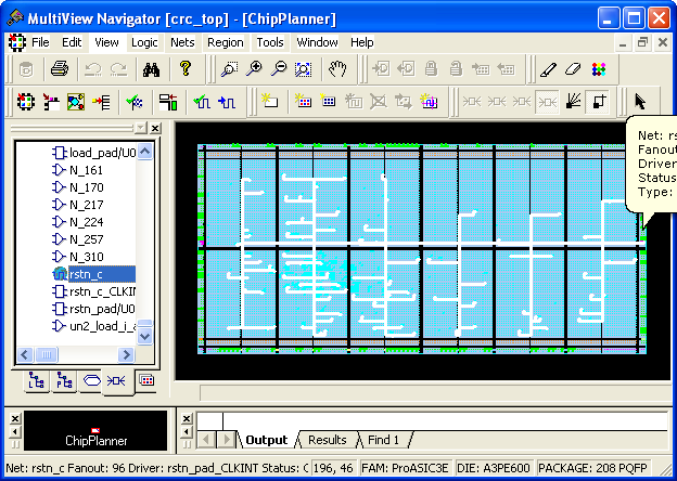
To display the Ratsnest view, select Show Ratsnest from the Nets menu or click the Ratsnest button. If any nets are selected, switching from Ratsnest view to Route view displays the routing tree.