
4.3.3 Spread Spectrum Clock Generation
(Ask a Question)In the CCC, each PLL is integrated with a Spread Spectrum Modulator (SSMOD) for Spread Spectrum Clock Generation (SSCG). The SSMOD is enabled or disabled using a CCC configurator. The SSMOD modulates the PLL output to spread the fundamental clock signal energy to a wide band of frequencies for reducing ElectroMagnetic Interference (EMI). The lowering of EMI enables significant reduction in expensive shielding cost and reduce interference with other sensitive circuits.
The SSCG capability is supported only when the PLL is placed in Fractional-N mode. Programming options include selection of center spread or down spread, modulation depth, and modulation shape.
The modulation frequency is the rate at which the spreading signal sweeps from the minimum to the maximum PLL output frequency. The modulation depth is represented by percentage spread, which defines the frequency range of the modulated clock resulting from the spread spectrum modulation.
The modulation shape is selectable between a triangular modulation profile and a pseudo random noise source.
The SSMOD works by modulating the feedback divider value of the PLL, thus modulating the PLLs output frequency between minimum and maximum value. For example, consider the case of a PLL with a reference clock of 20 MHz, an output frequency of 1 GHz, and a center spread modulation of 1.5%. The feedback divider is programmed to 50. The SSMOD then modulates the integer and fractional bits so that the PLL is configured with:
- A nominal divide value of 50
- A maximum divide value of 50.75 (FBDIV = 12'b000000110010, FRAC = 24'b110000000000000000000000)
- A minimum divide value of 49.25 (FBDIV = 12'b000000110001, FRAC = 24'b010000000000000000000000)
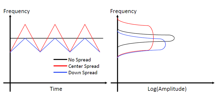
The following figure shows the frequency versus time and the resulting amplitude in the frequency domain.
The modulation frequency, modulation depth (spread), and spread mode are configurable in the CCC configurator. A SPREAD value of 0 turns off the modulation, a SPREAD value of 31 gives maximum modulation, and a value of 1 gives minimum modulation.
The following table lists the details of the modulation depth for a given SPREAD value, calculated as follows:
| SPREAD | Center Spread | Down Spread |
|---|---|---|
| 0 | 0 | 0 |
| 1 | ±0.1% | −0.1% |
| 2 | ±0.2% | −0.2% |
| 3 | ±0.3% | −0.3% |
| 4 | ±0.4% | −0.4% |
| 5 | ±0.5% | −0.5% |
| 6 | ±0.6% | −0.6% |
| ... | ... | ... |
| 29 | ±2.9% | −2.9% |
| 30 | ±3.0% | −3.0% |
| 31 | ±3.1% | −3.1% |
The modulation mode (Center versus Down spread) and the modulation amplitude depends on the amount of EMI reduction desired and the timing margin for logic running on the spread clock domain. The larger the spread value, the greater the reduction in the EMI amplitude. The larger the spread value, the more timing margin needed for the correct logic operation.