
3.6.4.24 RNBD451 Add On Board Example on SAM E51 Curiosity Nano Evaluation Kit
Description
This example demonstrates the BLE capability of RNBD451 Add On Board on SAM E51 Curiosity Nano Evaluation Kit.
This application connects to the MBD (Microchip Bluetooth Data) android application running on an Android Smartphone over Bluetooth low energy (BLE) using the RNBD451 Add On Board. The SAM E51 Curiosity Nano Evaluation Kit (MCU) is programmed to transmit data to a smartphone over BLE. The MCU device will send a Periodic Transmission of a single character. The configured LED blinks intermittently to indicate the occurrence of Periodic Transmission of Character when the RNBD module is connected. And LED turns OFF when the RNBD Device is disconnected from the Android Application.
Modules/Technology Used
- Peripheral Modules:
- GPIO
- SERCOM (USART)
Hardware Used
Software/Tools Used
This project has been verified to work with the following versions of software tools:
Refer Project Manifest present in harmony-manifest-success.yml under the project folder firmware/src/config/sam_e51_cnano.
- Refer the Release Notes to know the MPLAB X IDE and MCC Plugin version.
Because Microchip regularly updates tools, occasionally issue(s) could be discovered while using the newer versions of the tools. If the project does not seem to work and version incompatibility is suspected. It is recommended to double-check and use the same versions that the project was tested with. To download original version of MPLAB Harmony v3 packages, refer to document How to Use the MPLAB Harmony v3 Project Manifest Feature (DS90003305).
Setup
- Connect the SAM E51 Curiosity Nano Evaluation Kit to the Host PC as a USB Device through a Type-A male to micro-B USB cable connected to Micro-B USB (Debug USB) port.
- Adjust the PWR SEL (Power
Supply Selection) Jumper JP1 to the mikro 3V3 setting (i.e short J1 and
J2), designated for the mikroBUS interface on the RNBD451 Add-On Board as indicated in
the below image. By doing so, this configuration enables the RNBD module to draw power
directly from the MCU's power supply. This eliminates the necessity of using an
additional USB cable to power up the RNBD451 Add-On Board.

- Mount the RNBD451 Add On Board on
mikroBUS connector 2 of Curiosity Nano Base.

Programming Hex File
The pre-built hex file can be programmed by following the below steps.
- Open MPLAB X IDE.
- Close all existing projects in IDE, if any project is opened.
- Go to File -> Import -> Hex/ELF File.
- In the Import Image File
window,
- Create Prebuilt Project,
- Click the Browse button to select the prebuilt hex file.
- Select Device as ATSAME51J20A.
- Ensure the proper tool is selected under Hardware Tool and click on Next button.
- Select Project Name and Folder,
- Select appropriate project name and folder and click on Finish button
- Create Prebuilt Project,
- In MPLAB X IDE, click on Make and Program Device button to program the device.
- Follow the steps in Running the Demo section below.
Programming/Debugging Application Project
- Open the project (rnbd/firmware/sam_e51_cnano.X) in MPLAB X IDE.
- Ensure SAM E51 Curiosity Nano is selected as hardware tool to program/debug the application.
- Build the code and program the device by clicking on the Make and Program button in MPLAB X IDE tool bar.
- Follow the steps in Running the Demo section below.
- Debugging the project can be done by clicking on the Debug Main Project button in MPLAB X IDE toolbar.
Running the Demo

- Enable Bluetooth and location from Smartphone settings.
- Perform reset by unplugging and re-plugging the power cable of SAM E51 Curiosity Nano.
- Open the Microchip Bluetooth Data
(MBD) android app from the smartphone and tap on BLE Smart icon on the
dashboard. If prompted, allow the application to turn on Bluetooth.

- Search for RNBD451 Bluetooth device
under the BLE device window. The RNBD device should appear as RNBD451_FCC1
(deviceId) in the list of Bluetooth devices. And, click on it.

- Tap on the CONNECT device to
connect to the device.

- Once the Device is connected, expand
Microchip Data Service.

- Select Write Notify as shown in
the below image.

- Select Listen for notifications on the application.
- It may be required to enable
notification access to the app on the phone.
Data will begin to Send at a Periodic Rate to the device.
Data will become visible beneath the Notify/Listen Toggle option.
- Before Enabling the
Notify/Indicate Toggle button:

- After Enabling the
Notify/Indicate Toggle button, the Mobile App can read the data 31
HexValue which was sent from RNBD Module.

- Before Enabling the
Notify/Indicate Toggle button:
- It may be required to enable
notification access to the app on the phone.
Instructions to Add RNBD Functionality to the aApplication
The user could use this demonstration as an example to add RNBD functionality to the MPLAB Harmony v3 based application. Follow the below steps.
- Download the rnbd demo.
- From the folder rnbd/firmware/src, copy the folder click_routines to the folder firmware/src under the MPLAB Harmony v3 application project.
- Open MPLAB X IDE.
- Open the application project.
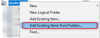
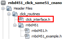
- In the project explorer, right click on
folder Header Files and add a sub folder click_routines by selecting
Add Existing Items from Folders...
- Click on Add Folder... button.
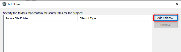
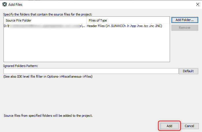
- Select the click_routines folder and select Files of Types as Header Files.
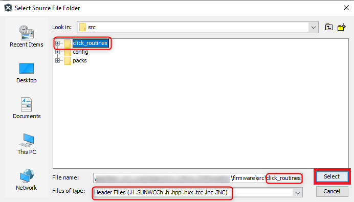
- Click on Add button to add the selected folder.
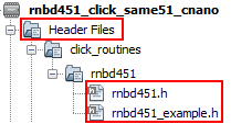
- The rnbd click example header files gets added to the project.
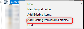
- In the project explorer, right click on folder Source Files and add a sub
folder click_routines by selecting Add Existing Items from Folders...
- Click on Add Folder... button.

- Select the click_routines folder and select Files of Types as Source Files.
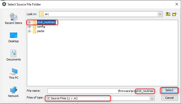
- Click on Add button to add the selected folder.
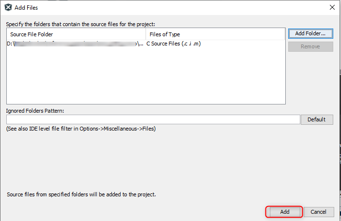
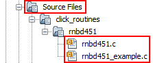
- The rnbd click example source files gets added to the project.
- The rnbd click example uses the USART and RNBD peripherals. The
configuration of these peripherals for the application depends on the 32-bit MCU and
development board the user is using.
- Configure USART:
- Add the SERCOM(USART) peripheral block to the MCC project graph.
- Configure USART Pins using MCC
Pin configuration Window.The USART configuration depends on:
- 32-bit MCU
- 32-bit MCU development board
- The socket on which the
user has mounted the RNBD451 Add On Board
Example: The rnbd click example on SAM E51 Curiosity Nano Evaluation Kit uses mikroBUS socket #2 on the Curiosity Nano Base for Click boards to mount the RNBD451 Add On Board. The USART lines from MCU coming to this socket are from the SERCOM0 peripheral on the MCU.
Figure 3-85. MCC Project Graph - USART Configuration 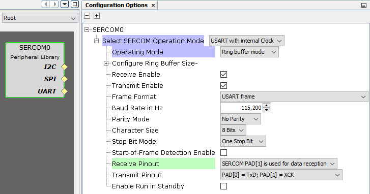
Figure 3-86. MCC Pin Configurator - USART Pin Configuration 
- Configure RNBD:
- Configure RNBD from
Wireless-> Drivers-> BLE block in the Resource Management tab of MCC
project graph.
The RNBD configuration depends on:
- SERCOM of MCU
Figure 3-87. MCC Project Graph - RNBD Configuration 
Example: Here RNBD uses SERCOM0 as a dependency to communicate MCU.
Figure 3-88. MCC Project Graph Window 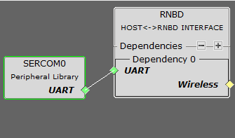
- SERCOM of MCU
- RNBD451 Add On Board need 1
additional GPIO pins as mentioned in the RNBD configuration.
Figure 3-89. MCC Pin Configurator - Bluetooth Reset (BT_RST) Pin Configuration 
- Configure RNBD from
Wireless-> Drivers-> BLE block in the Resource Management tab of MCC
project graph.
- Map Generic Macros:
- After generating the project, following the above configuration, map the generic macros used in the click routines to the Harmony PLIB APIs of the 32-bit MCU the project is running on.
- The generic macros should be
mapped in the header file click_interface.h.
Example: The rnbd click routines for the example on SAM E51 Curiosity Nano Evaluation Kit uses the following RNBD driver APIs.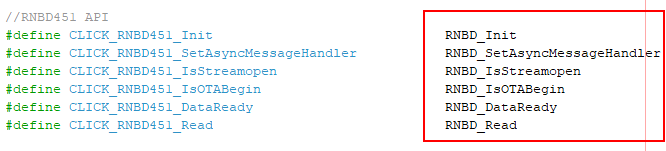
The click_routines folder contain an example C source file mchp_rnbd_example.c. The user could use mchp_rnbd_example.c as a reference to add rnbd functionality to the application.
- Configure USART:
Comments
- Reference Training Module:
- This application demo builds and
works out of box by following the instructions above in Running the Demo
section. If the user needs to enhance/customize this application demo, should use the
MPLAB Harmony v3 Software framework. Refer links below to setup and build the
applications using MPLAB Harmony.
- How to Setup MPLAB Harmony v3 Software Development Framework (DS90003232).
- How to Build an Application by Adding a New PLIB, Driver, or Middleware to an Existing MPLAB Harmony v3 Project (DS90003253).
- Video - How to Set up the Tools Required to Get Started with MPLAB® Harmony v3 and MCC
- Create a new MPLAB Harmony v3 project using MCC
- Update and Configure an Existing MHC-based MPLAB Harmony v3 Project to MCC-based Project