
3.6.4.18 LR Click Example on SAM E51 Curiosity Nano Evaluation Kit
Description
This example demonstrates the communication with LR (Lora) click. The application is designed to communicate with LR click by sending and receiving messages. The application reads the parameters firmware version, radio mode, and radio frequency from the LR click and displays it on a serial terminal of SAM E51 Curiosity Nano Evaluation Kit.
The RN2483 module’s architecture has three types of commands that can be used, and each allows access to different module functions:
- LoRaWAN Class A and Class C configuration and control, using the mac group of commands
- Low-level radio configuration and control, using the radio group of commands
- Other module functions, using the sys group of commands
In order to communicate with a LoRa network, a specific number of parameters need to be configured. Since two distinctive methods are offered for a device to become part of the network, each of these requires different parameters:
- Over-the-Air Activation (OTAA)
Where a device negotiates network encryption keys at the time it joins the network. For this, the device EUI (devEUI), application EUI (appEUI) and application key (appKey) need to be configured and then the OTAA procedure can start. All these keys will be provided by Lora gateway network providers, these keys can be loaded into RN2483 device using below commands.
- mac set deveui (devEUI)
- mac set appeui (appEUI)
- mac set appkey (appKey)
Once keys are loaded into RN2483, LR click can join the network using below command.
- mac join otaa
Once the connection is succesful, data can be transmitted using below command.
- mac tx (type) (portno) (data)
- Activation by Personalization (ABP)
Where the device already contains the network keys and can directly start communication with the network. Configuring the device address (address), network session key (nwkSessKey) and application session key (appSesskey) is sufficient for this type of initialization.All these keys will be provided by Lora gateway network providers, these keys can be loaded into RN2483 device using below commands.
- mac set devaddr (address)
- mac set nwkskey (nwkSessKey)
- mac set appskey (appSesskey)
Once keys are loaded into RN2483, LR click can join the network using below command
- mac join abp
Once the connection is succesful, data can be transmitted using below command
- mac tx (type) (portno) (data)
Refer RN2483 LoRa Technology Module Command Reference User’s Guide (DS40001784) for full command list and details.
Modules/Technology Used
- Peripheral Modules:
- EIC
- SYSTICK
- GPIO
- SERCOM (USART)
Hardware Used
Software/Tools Used
This project has been verified to work with the following versions of software tools:
Refer Project Manifest present in harmony-manifest-success.yml under the project folder firmware/src/config/sam_e51_cnano.
- Refer the Release Notes to know the MPLAB X IDE and MCC Plugin version.
- Any Serial Terminal application, such as Tera Term terminal application.
Because Microchip regularly updates tools, occasionally issue(s) could be discovered while using the newer versions of the tools. If the project does not seem to work and version incompatibility is suspected. It is recommended to double-check and use the same versions that the project was tested with. To download original version of MPLAB Harmony v3 packages, refer to document How to Use the MPLAB Harmony v3 Project Manifest Feature (DS90003305).
Setup
- Mount the LR click board on mikroBUS connector 1 of Curiosity Nano Base.
- Connect the SAM E51 Curiosity Nano
Evaluation Kit to the Host PC as a USB Device through a Type-A male to micro-B USB
cable connected to Micro-B USB (Debug USB) port.

Programming Hex File
The pre-built hex file can be programmed by following the below steps.
- Open MPLAB X IDE.
- Close all existing projects in IDE, if any project is opened.
- Go to File -> Import -> Hex/ELF File.
- In the Import Image File
window,
- Create Prebuilt Project,
- Click the Browse button to select the prebuilt hex file.
- Select Device as ATSAME51J20A.
- Ensure the proper tool is selected under Hardware Tool and click on Next button.
- Select Project Name and Folder,
- Select appropriate project name and folder and click on Finish button
- Create Prebuilt Project,
- In MPLAB X IDE, click on Make and Program Device button to program the device.
- Follow the steps in Running the Demo section below.
Programming/Debugging Application Project
- Open the project (sam_e51_cnano/same51n_mikroe_click/lr/firmware/sam_e51_cnano.X) in MPLAB X IDE
- Ensure SAM E51 Curiosity Nano is selected as hardware tool to program/debug the application
- Build the code and program the device by clicking on the Make and Program Device button in MPLAB X IDE tool bar
- Follow the steps in Running the Demo section below
Running the Demo
- Open the Tera Term terminal application on the PC (from the Windows Start menu by pressing the Start button).
- Set the baud rate to 115200.
- For every switch press, the SAM E51
Curiosity Nano Evaluation Kit prints the parameters of LR click.

Instructions to Add LR Functionality to the Application
The user could use this demonstration as an example to add LR functionality to the MPLAB Harmony v3 based application. Follow the below steps.
- If the user has not downloaded the LR demo yet Click Here to download, otherwise go to next step.
- Unzip the downloaded .zip file.
- From the unzipped folder lr/firmware/src, copy the folder click_routines to the folder firmware/src under the MPLAB Harmony v3 application project.
- Open MPLAB X IDE.
- Open the application project.
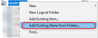
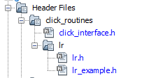
- In the project explorer, right click on
folder Header Files and add a sub folder click_routines by selecting
Add Existing Items from Folders...
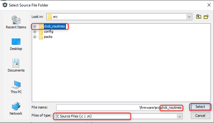
- Click on Add Folder... button.
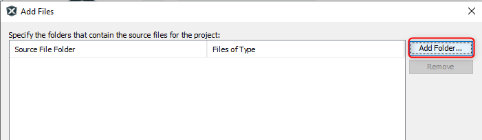
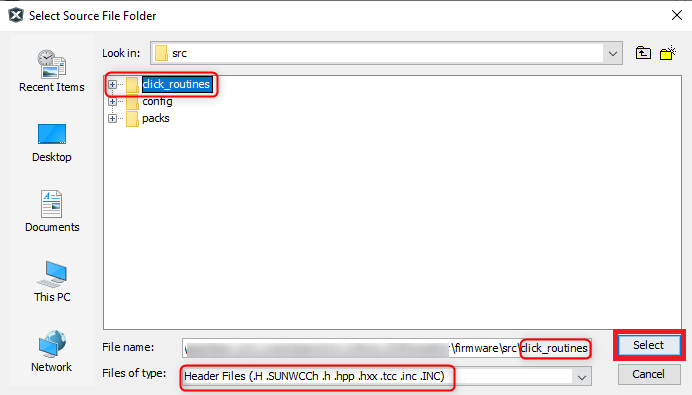
- Select the click_routines folder and select Files of Types as Header
Files.
- Click on Add button to add the selected folder.
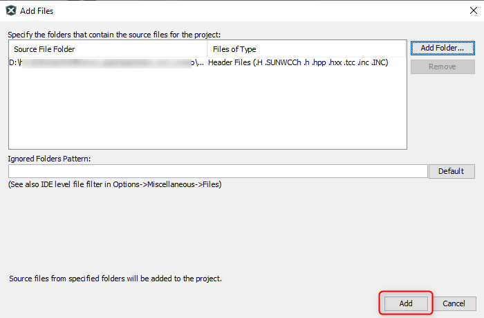
- The LR click example header files gets added to the project.
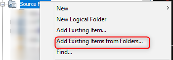
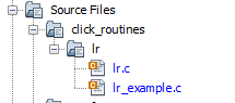
- In the project explorer, right click on folder Source Files and add a sub
folder click_routines by selecting Add Existing Items from Folders...
- Click on Add Folder... button.

- Select the click_routines folder and select Files of Types as Source
Files.
- Click on Add button to add the selected folder.
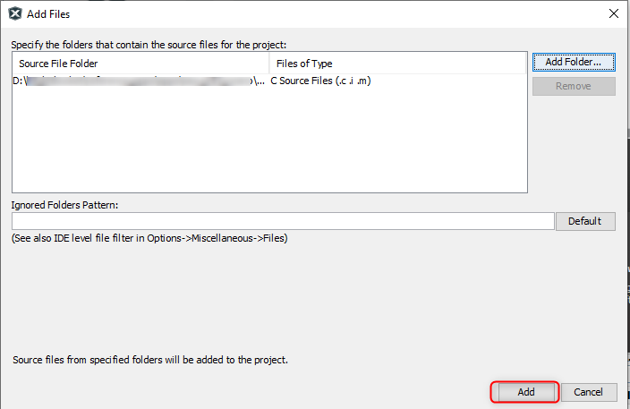
- The LR click example source files gets added to the project.
- The LR click example uses the USART and Timer peripherals. The
configuration of these peripherals for the application depends on the 32-bit MCU and
development board the user is using.
- Configure USART:
- Add the USART peripheral block to the MCC project graph.
- Configure USART Pins using MCC
Pin configuration Window.The USART configuration depends on:
- 32-bit MCU
- 32-bit MCU development board
- The socket on which the
user has mounted the LR click board
Example: The LR click example on SAM E51 Curiosity Nano Evaluation Kit uses mikroBUS socket #1 on the Curiosity Nano Base for Click boards to mount the LR click board. The USART lines from MCU coming to this socket are from the SERCOM4 peripheral on the MCU.
Figure 3-61. MCC Project Graph - USART Configuration 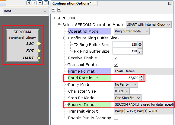
Figure 3-62. MCC Pin Configurator - USART Pin Configuration 
- Configure LR Click Reset
Pin:
- Configure LR Click Reset Pin
using MCC Pin configuration Window.The Reset Pin configuration depends on:
- The socket on which the
user has mounted the LR click board
Example: The LR click example on SAM E51 Curiosity Nano Evaluation Kit uses mikroBUS socket #1 on the Curiosity Nano Base for Click boards to mount the LR click board. The Reset Pin line from the LR Click coming to this socket is PA07 on the MCU.
Figure 3-63. MCC Pin Configurator - Reset Pin Configuration 
- The socket on which the
user has mounted the LR click board
- Configure LR Click Reset Pin
using MCC Pin configuration Window.
- Configure Timer:
- Configure Timer peripheral
block in the MCC project graph.The Timer configuration depends on:
- 32-bit MCU
Example: The LR click example on SAM E51 Curiosity Nano Evaluation Kit uses SysTick timer module on the MCU to implement the time requirement of LR click routines.
Figure 3-64. MCC Project Graph - SysTick Configuration 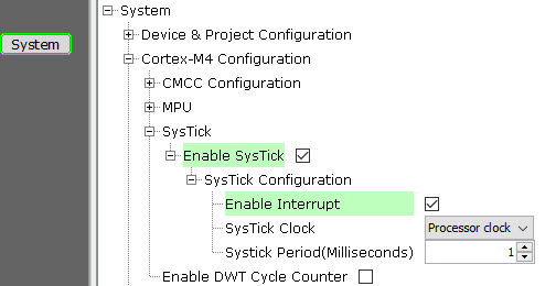
- 32-bit MCU
- Configure Timer peripheral
block in the MCC project graph.
- Map Generic Macros:
- After generating the project, following the above configuration, map the generic macros used in the click routines to the Harmony PLIB APIs of the 32-bit MCU the project is running on.
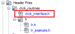
- The generic macros should be
mapped in the header file click_interface.h.
Example: The LR click routines for the example on SAM E51 Curiosity Nano Evaluation Kit uses the following Harmony PLIB APIs.
The click_routines folder contain an example C source file lr_example.c. The user could use lr_example.c as a reference to add LR functionality to the application.
- Configure USART:
Comments
- Reference Training Module:
- This application demo builds and
works out of box by following the instructions above in Running the Demo
section. If the user needs to enhance/customize this application demo, should use the
MPLAB Harmony v3 Software framework. Refer links below to setup and build the
applications using MPLAB Harmony.
- How to Setup MPLAB Harmony v3 Software Development Framework (DS90003232).
- How to Build an Application by Adding a New PLIB, Driver, or Middleware to an Existing MPLAB Harmony v3 Project (DS90003253).
- Video - How to Set up the Tools Required to Get Started with MPLAB® Harmony v3 and MCC
- Create a new MPLAB Harmony v3 project using MCC
- Update and Configure an Existing MHC-based MPLAB Harmony v3 Project to MCC-based Project