
3.6.4.13 WIFI 7 Click Board Example on SAM E51 Curiosity Nano Evaluation Kit
Description
This example demonstrates the WiFi capability of WiFi 7 Click board on SAM E51 Curiosity Nano Evaluation Kit.
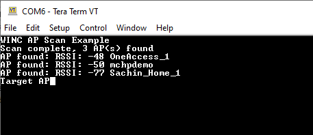
This application scans for available Access Points and display the list on Tera term. It sends out a scan requests and lists responses of all Access points along with their signal strength and connects to the specified Access point.
Modules/Technology Used
- Peripheral Modules:
- GPIO
- SERCOM (SPI)
- SERCOM (UART)
- Core
- SPI Driver
- WINC
- Timer system service
- TC0
- Console system service
- Debug system service
ATWINC1510 Firmware Upgrade Guide
Refer the documentation in utilities folder
Hardware Used
Software/Tools Used
This project has been verified to work with the following versions of software tools:
Refer Project Manifest present in harmony-manifest-success.yml under the project folder firmware/src/config/sam_e51_cnano.
- Refer the Release Notes to know the MPLAB X IDE and MCC Plugin version.
- Any Serial Terminal application, such as Tera Term terminal application.
Because Microchip regularly updates tools, occasionally issue(s) could be discovered while using the newer versions of the tools. If the project does not seem to work and version incompatibility is suspected. It is recommended to double-check and use the same versions that the project was tested with. To download original version of MPLAB Harmony v3 packages, refer to document How to Use the MPLAB Harmony v3 Project Manifest Feature (DS90003305).
Setup
- Connect the SAM E51 Curiosity Nano Evaluation Kit to the Host PC as a USB Device through a Type-A male to micro-B USB cable connected to Micro-B USB (Debug USB) port.
- Mount the WiFi 7 click board on
mikroBUS connector 1 of Curiosity Nano Base.

Programming Hex File
The pre-built hex file can be programmed by following the below steps.
- Open MPLAB X IDE
- Close all existing projects in IDE, if any project is opened.
- Go to File -> Import -> Hex/ELF File.
- In the Import Image File
window,
- Create Prebuilt Project,
- Click the Browse button to select the prebuilt hex file.
- Select Device as ATSAME51J20A.
- Ensure the proper tool is selected under Hardware Tool and click on Next button.
- Select Project Name and Folder,
- Select appropriate project name and folder and click on Finish button
- Create Prebuilt Project,
- In MPLAB X IDE, click on Make and Program Device button to program the device.
- Follow the steps in Running the Demo section below.
Programming/Debugging Application Project
- Open the project (wifi_7/firmware/sam_e51_cnano.X) in MPLAB X IDE
- Ensure SAM E51 Curiosity Nano is selected as hardware tool to program/debug the application
- Build the code and program the device by clicking on the Make and Program button in MPLAB X IDE tool bar
- Follow the steps in Running the Demo section below
Running the Demo
- Configure the serial port terminal with 9600 baud rate.
- After power up, when the demo is
running, the application prints as shown below.
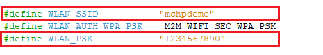
- Change the SSID and Password of the
known WiFi credentials in "wifi_7.h" header file and reprogram the project.
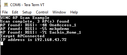
- Device connects to the specified WiFi
Access Point.
Instructions to Add WiFi 7 Click Functionality to the Application
The MPLAB Harmony v3 supports adding WiFi functionality to the application using WINC driver.
Below are Harmony v3 configuration for the WiFi 7 click.
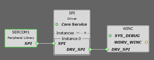
- Connect the WINC components as shown in
the below figure.
- Change Configuration of
components as shown in the below figures.
Figure 3-41. SERCOM1 Configuration 
Figure 3-42. MCC Pin Configurator - SPI Pin Configuration 
Figure 3-43. MCC Pin Configurator - Additional Pin Configurations 
Figure 3-44. WINC Configuration  Note: Other component´s configurations will be default.
- Change Configuration of
components as shown in the below figures.
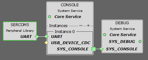
- Connect the console and debug system service necessary for WINC driver as shown in the
below figure.
- Change Configuration of components
as shown in the below figures.
Figure 3-45. SERCOM5 Configuration 
Figure 3-46. MCC Pin Configurator - UART Pin Configuration 
Figure 3-47. Debug Configuration 
- Change Configuration of components
as shown in the below figures.
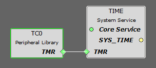
- Enable timer system service and core service as needed by the WINC driver.

- Configure the EIC as shown in the below figure.

- The user could use this demonstration as an example to add WiFi 7 click functionality
to the MPLAB Harmony v3 based application. Follow the below steps.Note: This demo can be extended to connect to web to transfer data, refer the reference section below for more applications.
- If the user has not downloaded the WiFi 7 click demo yet Click Here to download, otherwise go to next step.
- Unzip the downloaded .zip file.
- From the unzipped folder wifi_7/firmware/src, copy the folder click_routines to the folder firmware/src under the MPLAB Harmony v3 application project.
- Open MPLAB X IDE
- Open the application project
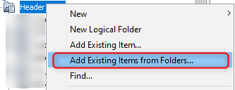
- In the project explorer, right
click on folder Header Files and add a sub folder click_routines by
selecting Add Existing Items from Folders...
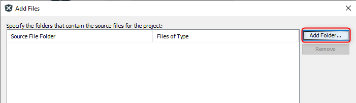
- Click on Add Folder... button.
- Select the click_routines folder and select Files of Types as Header
Files.
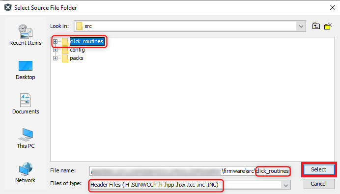
- Click on Add button to add the selected folder.
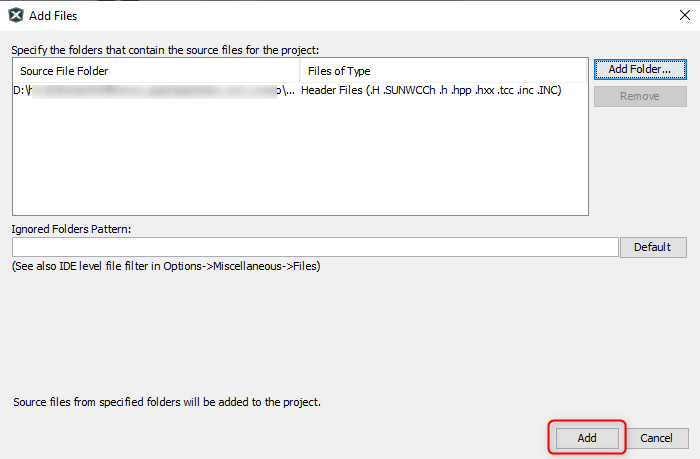
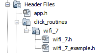
- The WiFi 7 click header files gets added to the project.
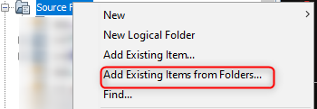
- In the project explorer, right click on folder Source Files and add a sub
folder click_routines by selecting Add Existing Items from
Folders...
- Click on Add Folder... button.

- Select the click_routines folder and select Files of Types as Source
Files.
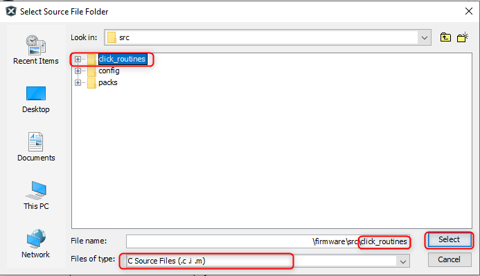
- Click on Add button to add the selected folder.
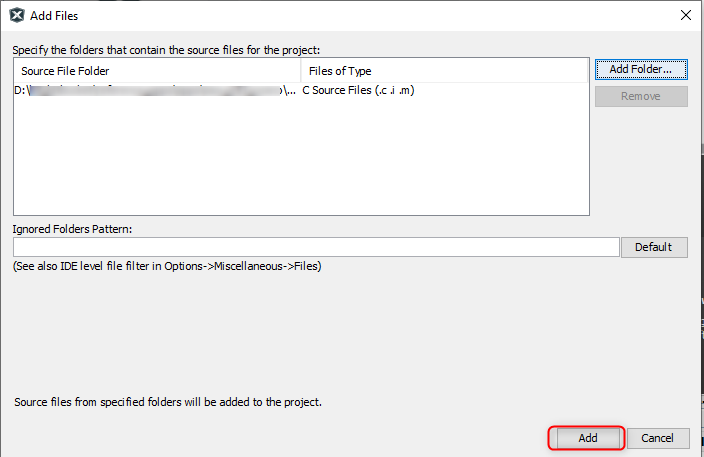
- The WiFi 7 click source files gets added to the project.
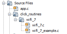
The click_routines folder contain an example C source file wifi_7_example.c. The user could use wifi_7_example.c as a reference to add WiFi 7 display functionality to the application.
Comments
- Reference Training Module:
- Getting Started with Harmony v3 Peripheral Libraries on SAM D5x/E5x MCUs
- Low Power Application on SAM E54 (Arm® Cortex® M4) MCUs Using MPLAB® Harmony v3 Peripheral Libraries
- Getting Started with Harmony v3 Drivers on SAM E54 MCUs Using FreeRTOS
- Google Cloud IoT Core Application on SAM E51 Curiosity Nano Evaluation Kit using Socket mode
- Vending Machine Application on SAM E54 Xplained Pro Evaluation Kit using TCP/IP mode
- This application demo builds and
works out of box by following the instructions above in Running the Demo
section. If the user needs to enhance/customize this application demo, should use the
MPLAB Harmony v3 Software framework. Refer links below to setup and build the
applications using MPLAB Harmony.
- How to Setup MPLAB Harmony v3 Software Development Framework (DS90003232).
- How to Build an Application by Adding a New PLIB, Driver, or Middleware to an Existing MPLAB Harmony v3 Project (DS90003253).
- MPLAB Harmony v3 is configurable through MPLAB Code Configurator (MCC). Refer to the below links for specific instructions to use MPLAB Harmony v3 with MCC.