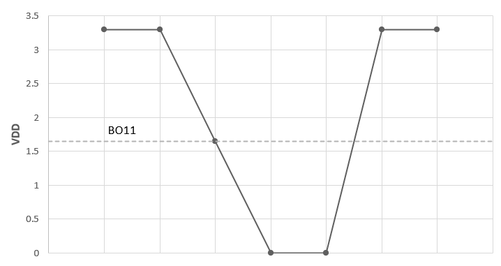
30.7 Brown-out Reset (BOR)
The Brown-out Reset (BOR) module is based on an internal voltage reference circuit that monitors the regulated supply voltage. The main purpose of the BOR module is to generate a device Reset when a Brown-out condition occurs. Brown-out conditions are generally caused by glitches on the AC mains (for example, missing portions of the AC cycle waveform due to bad power transmission lines or voltage sags due to excessive current draw when a large inductive load is turned on).
A BOR generates a Reset pulse which resets the device. The BOR selects the clock source based on the device Configuration bit selections.
If an Oscillator mode is selected, the BOR activates the Oscillator
Start-up Timer (OST). The system clock is held until OST expires. If the PLL is used, the
clock is held until the LOCK bit (OSCCON[5]) is ‘1’.
The BOR status bit (RCON[1]) is set to indicate that a BOR has occurred. The BOR circuit continues to operate while in Sleep or Idle mode and resets the device should VDD fall below the BOR threshold voltage.
If VDD is between VBOR - 25 mV and VBOR, a BOR reset may repeatedly occur. However, while operating at a VDD between 3 - 3.6V, the device will operate as expected. A tristate IO can be used to observe this behavior. The VBOR specification is listed in the Electrical Characteristic section. An external voltage monitor IC may be used to avoid this behavior. MCP111-300E and similar devices are recommended for this purpose.