
2.7.2 Place and Route
(Ask a Question)The place and route process requires the following steps to be completed:
- Selecting the already imported io_constraints.pdc file
- Placing the PF_DDR3_C0_0 block using the I/O Editor
- Ensuring all the I/Os are locked
To perform place and route, follow these steps:
- Double-click Manage Constraints on the Design Flow tab.
- On the I/O Attributes tab, enable the check box next to the io_constraints.pdc file, as shown in the following figure. The io_constraints.pdc file contains the I/O assignment for reference clock, UART, GPIO, and SPI interfaces, and other top-level I/Os.
Figure 2-28. I/O Attributes 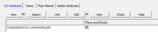
- From the Edit drop-down list, select Edit with I/O Editor, as shown in the following figure.
Figure 2-29. Edit with I/O Editor Option 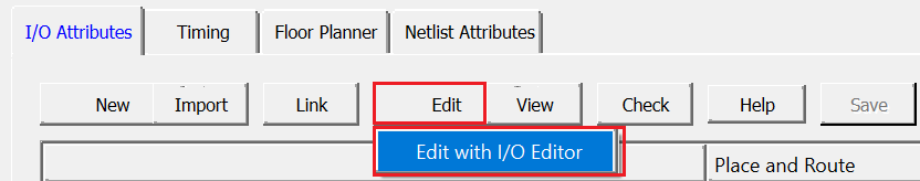
- In the I/O Editor, click the Port View [active] tab, and lock the CTRLR_READY port to pin C27, as shown in the following figure. This ensures that the CTRLR_READY port is assigned to pin C27, which is connected to an user LED for debug purposes.
Figure 2-30. Port View 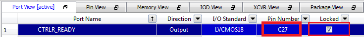
- To place the DDR3 I/O lanes, in the I/O Editor
Design View, click the Port tab in the left pane, and select
DDR3, as shown in the following figure.
Figure 2-31. I/O Editor Design View – DDR3 Selection 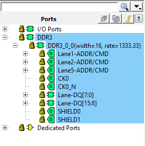
- Drag and place the DDR3 subsystem on the
NORTH_NE side, as shown in the following figure. The DDR3
memory on the board is connected to DDR I/Os present on the north-east side.
Figure 2-32. Memory View [active] Tab with DDR3 Subsystem Placement 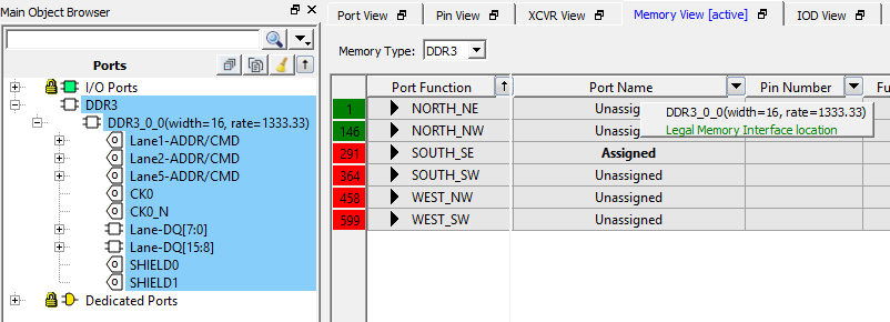
The DDR3 subsystem is placed on the NORTH_NE side, as shown in the following figure.
Figure 2-33. PF_DDR3_C0_0 Placed 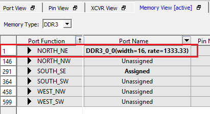
- From I/O Editor Port View
tab, check if there are any unlocked I/Os, and lock them as mapped in the
io_constraints.pdcfile available in the Design_Files_Directory\HW\src\constraints folder. - Click Save.
- Close the I/O Editor.
A
user.pdcfile is created for PF_DDR3_C0_0 block in the and Floor Planner tabs.Important: PF_DDR3_C0_0 can also be placed using thefp_constraints.pdc. Import thefp_constraints.pdcfrom tab and select the place and route option after synthesis. This constraint file is available in the Design_Files_Directory\HW\src\constraints folder.When place and route is successful, a green tick mark appears next to Place and Route.
- Double-click Place and
Route from the Design Flow tab.Important: The user has to enable the High Effort Layout and Repair Minimum Delay Violation option in the Place and Route settings to meet the timing requirements.