10.5.1.1.1 Type 1 vs. Type 2
In Flash*Freeze Type 1, entering and exiting the mode is controlled by the assertion and deassertion of the Flash*Freeze pin. In order to use Flash*Freeze Type 1 you must instantiate INBUF_FF at the top level directly.
In Flash*Freeze Type 2, entering and exiting the mode is controlled by both the Flash*Freeze pin and the user-defined LSICC signal available in the ULSICC macro.
See the following table for Flash*Freeze (FF) pin assertion and deassertion values.
| Signal | Assertion Value | Deassertion Value |
|---|---|---|
| Flash*Freeze (FF) Pin | Logic 0 | Logic 1 |
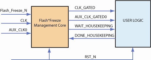
Microchip recommends that clock domains that require state-saving during Flash*Freeze have the clock routed through the Flash*Freeze Management core.
FlashFreeze_FSM
The FlashFreeze_FSM runs in the following order:
- The FSM makes sure that Flash*Freeze pin is asserted and persistent.
- The FSM signals to user logic to complete critical operations that are still in process with the signal WAIT_HOUSEKEEPING.
- User logic indicates that critical operations are complete through the signal DONE_HOUSEKEEPING.
- The FSM stops the clock connected to user logic using the Filter.
- The FSM takes the device into Flash*Freeze mode by asserting the LSICC input of the ULSICC macro instantiated inside the Flash*Freeze Management core.
- The device enters Flash*Freeze mode.
- When the Flash*Freeze pin is de-asserted, the FSM wakes up. If it wakes up in the incorrect state it self-recovers.
- On wake-up, the FSM de-asserts the LSICC input and releases the clock to user logic. This enables the FSM to protect the user logic from narrow pulses on the clock and allows critical processes to finish.
- Filter
- Filters the clocks to user logic based on the control signal received from the FSM; uses the CLKINT global buffer.
A minimum of one Filter exists in the core. There are 17 filters available in the core. The FSM is clocked by the primary clock specified by the user.
HouseKeeping
Your design can enter Flash*Freeze mode at any time, even in the middle of critical tasks. Rather than stop the design clock immediately (as a prelude to entering Flash*Freeze), housekeeping enables you to delay it until the tasks are complete.
User logic determines when the user logic clock stops after the Flash*Freeze pin was asserted.
The housekeeping feature is optional. If you do not use it you can configure Flash*Freeze to bypass housekeeping. To do so, disable Enable Houskeeping in the GUI. This loops back the Wait_Housekeeping output with the Done_Houskeeping input.
The following image shows the Flash*Freeze use model.