1.1.1.6.1 CDR Options
(Ask a Question)The PMA of each lane includes a PLL used for the receiver CDR. The CDR PLL supports lock-to-reference and lock-to-data modes, which allows customization of the CDR options best suited for the application. It also includes a Burst-mode receiver option, which can switch between both options that are selectable through the Libero transceiver configurator.
Lock-to-Reference: The phase frequency detector (PFD) in the CDR tracks the receiver input reference clock. The PFD controls the charge pump that tunes the VCO in the CDR. The LOCK status signal is asserted high to indicate that the CDR has locked to the phase and frequency of the receiver input reference clock regardless of the data phase detector (PD). Lock-to-reference is used to lock the transceiver CDR to the reference clock rather than the incoming data when the receiver is used as a simple over-sampler, or when the CDR must be locked to a local oscillator.
Lock-to-Data: The CDR must use the lock-to-data mode to recover the clock and data from the incoming serial data. In this mode, the data phase detector of the CDR tracks the incoming serial data at the receiver input. Depending on the phase difference between the incoming data and the CDR output clock, the PD controls the CDR charge pump that adjusts the VCO. The LOCK status signal is asserted when the CDR finds valid data. The actual lock time depends on the incoming data stream's transition density.
Burst Mode Receiver: The transceiver CDR circuit has enhanced capabilities to support burst mode receivers (BMR). BMR is used in NGPON2 and 10GEPON passive optical network applications for fast and bounded lock times. The BMR option is used to implement the fast clock-data recovery when the conventional bang-bang phase detector PLLs cannot meet the stringent lock times required by the passive optical network (PON) applications.
When BMR mode is selected, LANE_X_CDR_LOCKMODE[1:0] are exposed for CDR mode control. The following table lists the value and the description of the CDR lock mode control bits.
| LANE_X_CDR_LOCKMODE[1:0] Values | Mode |
|---|---|
| 2’b00 | Not used |
| 2’b01 | High gain1 |
| 2’b10 | Lock to reference |
| 2’b11 | Normal Mode2 |
- High Gain mode is used during Preamble/delimiter detection phase to fast phase lock to the incoming RX data. This mode might generate additional clock jitter on the recovered clock. Once the preamble/de-limiter is detected, it is recommended to switch to normal CDR mode to minimize jitter.
- This is used when payload is received from Burst mode receiver.
For detailed CDR specifications, see respective PolarFire FPGA Datasheet and PolarFire SoC Datasheet . For application example and implementation details, see PolarFire Burst Mode Receiver Demo Guide.
Lock to Data with 2X Gain: This transceiver option implements the fast clock-data recovery when incoming data streams such as stressful SDI patterns require high gain to quickly phase lock to the incoming pattern. This mode produces faster lock times than that of normal Lock to data mode.
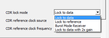
CDR_GAIN parameter is not set to
"Low".The following figure shows the CDR Lock mode options.