For the PIC32WM-BZ6602 Module, a 2.4 GHz chip antenna is
integrated into the design. The layers on the module below the antenna do not have
copper traces. The recommendation is to mount the PIC32WM-BZ6602 Module on the edge of the host board and ensure no copper
material exists below the antenna structure of the PIC32WM-BZ6602 Module, as well as no copper traces or planes on the host board
in that area.
The following table lists the technical specifications of the chip antenna when the user
tests it by mounting the PIC32WM-BZ6602 module on an
evaluation board.
Table 5-2. Chip Antenna Specification for PIC32WM-BZ6602
Module
Parameter
Specification
Operating frequency
2400 to 2500 MHz
Peak gain
-2.0 dBi at 2442 MHz
Efficiency
29%
Chip Antenna Radiation Pattern
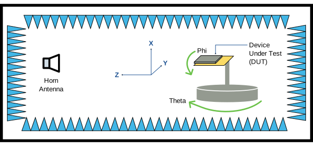
The following figure illustrates the PIC32WM-BZ6602 module
orientation in the measurement system for the chip antenna’s radiation pattern.Figure 5-12. Chip Antenna Radiation Pattern Placement
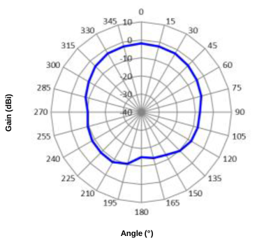
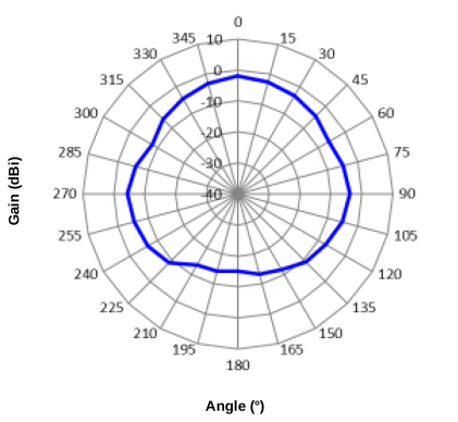
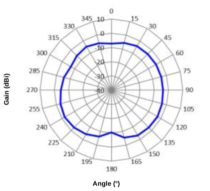
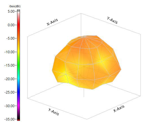
The following figures illustrate the antenna radiation patterns for the PIC32WM-BZ6602 Module.Figure 5-13. PIC32WM-BZ6602 Antenna Radiation Pattern when
Phi = 0°Figure 5-14. PIC32WM-BZ6602 Antenna Radiation Pattern when
Phi = 90°Figure 5-15. PIC32WM-BZ6602 Antenna Radiation Pattern when
Theta = 90°Figure 5-16. PIC32WM-BZ6602 Antenna Radiation 3D
Pattern
DS00005998E
The online versions of the documents are provided as a courtesy. Verify all content and data in the device’s PDF documentation found on the device product page.