
1.3.3.1 Master Windows
(Ask a Question)Master windows translate the addresses from PCIE domain to AXI 4 domain.
When the PCIESS is in endpoint mode, there is direct mapping between the BAR and the address tables, as shown in the following figures.
Each 32-bit BAR has an address translation table (ATR). The PCIe implementation supports up to six 32-bit base address registers (BARs). Each BAR is 32 bits, but two BARs can be combined to make a 64-bit BAR. For example, BAR0 (address offset 010h) and BAR1 (address offset 014h) can be combined to form a 64-bit BAR01.
For a 64-bit BAR mapping, address tables are used as follows:
- BAR01 targets ATR0, and ATR1 remains unused
- BAR23 targets ATR2, and ATR3 remains unused
- BAR45 targets ATR4, and ATR5 remains unused


The PCIESS Configurator in Libero SoC software provides a GUI to configure the BAR settings for an endpoint application.
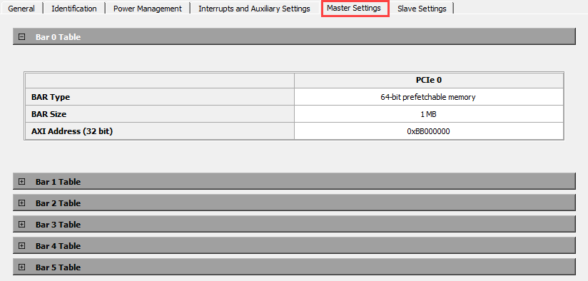
The following figure shows an example of configuring Master settings to map the BAR0 transactions to PCIe AXI master IF transactions for AXI address 0xBB000000.

If BAR0 receives write/read request with offset 1010, then ATR0 translates this address to 0xBB001010.

When the PCIESS is in root port mode (Figure 5), up to six translation tables (currently, Libero SoC supports two translation tables) can be implemented. When transferring PCI Express receive requests to the AXI master, the bridge performs a windows match using the PCIe 64-bit address. If a match is found, the bridge forwards the request to the desired AXI4 master interface and adds the corresponding AXI base address.
When the PCI Express BAR0/1 are configured as a 64-bit prefetchable memory space of 16 Kbytes, PCIe read and write requests targeting BAR0 or BAR1 are routed to the bridge configuration space. This memory space operates in the following two ways:
- When I/O or prefetchable memory windows are implemented, PCIe read and write requests targeting I/O or prefetchable memory windows are routed to the PCIe window address translation module.
- When I/O or prefetchable memory windows are not implemented, PCIe read and write requests that do not target BAR0 or BAR1 are routed to the PCIe window address translation module.

The following figure shows an example of configuring Master settings to map the PCIe RP address space to PCIe AXI master IF address space for AXI address 0xBB000000.
When PCIe receives write/read request at address 0x00001010, this address is mapped to ATR0, which removes the upper 44 bits (depending on table size) and adds the translation address 0xBB000000 to offset 0x1010.
