Mount the RNWF11 Add On Board on SAME54 Xplained Pro
Evaluation Kit at respective header. For more details about the boards
placement, refer Figure 6-37.
Connect the debugger USB port on
the SAME54 Xplained Pro evaluation kit to computer using a micro USB cable.
Change the configuration. There
are two options to change the configuration:
Option 1: Change the
configuration manually in the code.
Open the code in
MPLAB IDE v6.00 or higher and add Home AP and device information
in the application code.
In
configuration.h, add Wi-Fi
configurations in
SYS_RNWF_WIFI_STA_SSID,
SYS_RNWF_WIFI_STA_PWD,
SYS_RNWF_STA_SECURITY.
In
configuration.h, user can setup the
Root CA Certificate and the name of the server using
macros SYS_RNWF_NET_ROOT_CERT0 and
SYS_RNWF_NET_SERVER_NAME0. These
macros allow to define the name of the server that the
TLS Client must connect.
Option 2: Change the
configuration via MCC.
For more details
about Wi-Fi configurations, refer Figure 3-31.
The
following fields can be configured via MCC Wi-Fi
settings:
SSID
Passphrase
Security Type
For more details
about TLS configurations, refer Figure 3-40.
The
following fields can be configured via MCC Net Sock
settings - TLS;
Root CA
Server Name
Save the changes, then build and
program the code to the hardware using MPLAB X IDE.Figure 6-46. Programming the
Board
Open the Terminal application
(for example, Tera Term or PuTTY) on the PC
Connect to the “USB to UART” COM
port and configure the serial settings as follows:
Baud: 115200
Data: 8 Bits
Parity: None
Stop: 1 Bit
Flow Control:
None
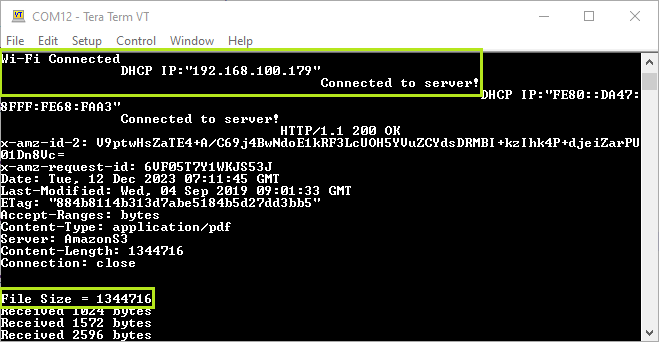
As the board boots up, it will
connect to Home-AP and prints the IP address obtained. The board will establish
a connection with AWS S3. After establishing a successful TLS server-client
connection, the application will try to access/read the document listed.Figure 6-47. TLS Client Serial
Logs
Once the device receives entire
document, Receive Complete message is printed on serial console
as illustrated in the following figure.Figure 6-48. TLS Client Serial
Logs