
7.3 Running TFTP Demo
(Ask a Question)This section describes how to run the IAP using TFTP. The following procedure assumes that the serial terminal is setup. For more information about setting up the serial terminal, see Tera Term Setup.
Before you begin, perform the following steps:
- Connect the power supply cable to the J9 connector on the board.
- Connect the USB cable from the host PC to J5 Future Technology Devices International Limited (FTDI) port on the board.
- Open pin 1 and 2 of the J23 jumper.
- Power-up the board using the SW3 slide switch.
- Ensure that the device is programmed
with the
gbe_tftp_iap_v1.jobfile and the external SPI Flash is programmed with the application. See Program SPI Flash Image to program the external SPI Flash. - Enable TFTP client in Host PC. To enable the TFTP client in Host PC, see Appendix 1: Enable TFTP Client.
After power-up, Tera Term displays the options as shown in the following figure. Observe the design version 01 in the device.
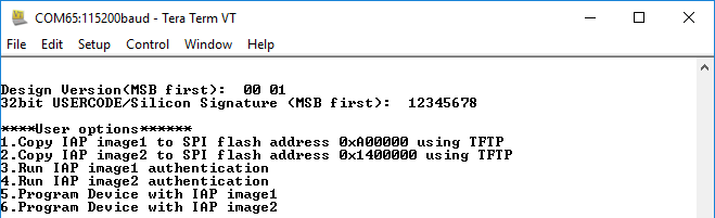
After power-up, perform the following steps:
- Press 1 to load IAP Image1 to SPI Flash address 0xA00000 using TFTP.
- Press e to
erase the SPI Flash memory location (0xA00000 - 0x13FFFFF).
Figure 7-7. Erasing SPI Flash Memory Location [0xA00000 - 0x13FFFFF] 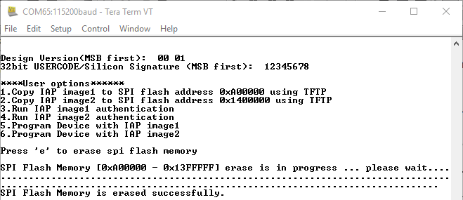
- After completion of the SPI Flash
erase operation, the Ethernet link is up, and the IP address is displayed on the
Tera Term terminal. In this example, the IP address is 10.60.132.61. The TFTP
command uses this IP address to transfer the file to the external SPI Flash. The LED
G1 on the PolarFire Evaluation Kit board starts blinking. To use the design in
static IP mode, see Running the Design in Static IP Mode.
Figure 7-8. Acquiring IP Address 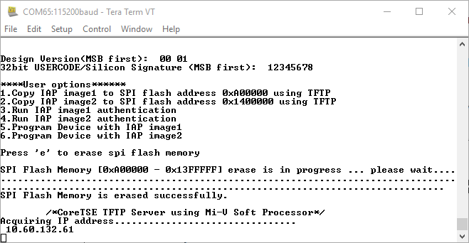
- On the Host PC command prompt, browse to the folder <$design file directory>\mpf_an4569_v2023p2_eval_df\tftp_iap\iap_images.
- Type the
tftp -i 10.60.132.61
                    PUT iog_cdr_tftp_iap_v2.spi
command to transfer theiog_cdr_tftp_iap_v2.spiprogramming file to the SPI Flash as shown in the following figure.Figure 7-9. Transfer Programming Image1 
- Wait until total bytes received
message to ensure that the programming image1 is transferred to the SPI Flash. On
completion of the Image1 transfer, the user options are displayed.
Figure 7-10. Bytes Received for Image1 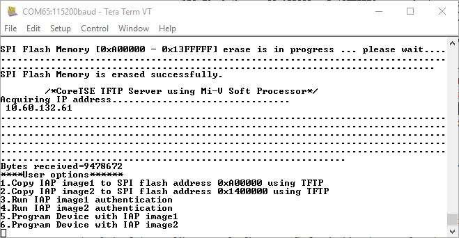
- Press 2 to load IAP Image2 to SPI Flash address 0x1400000 using TFTP.
- Press e to
erase the SPI Flash memory location (0x1400000 - 0x1DFFFFF).
Figure 7-11. Erasing the SPI Flash Memory Location [0x1400000 - 0x1DFFFFF] 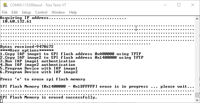
- On the Host PC command prompt, ensure to browse the folder <$design file directory>\mpf_an4569_v2023p2_eval_df\tftp_iap\iap_images.
- Type the
tftp -i 10.60.132.61
                    PUT iog_cdr_tftp_iap_v3.spi
command to transfer the programming image2 as shown in the following figure.Figure 7-12. Transfer IAP Image2 
- Wait until total bytes received
message to ensure that the programming image2 is transferred to the SPI Flash. On
completion of the Image2 transfer, the user options are displayed.
Figure 7-13. Bytes Received for Image2 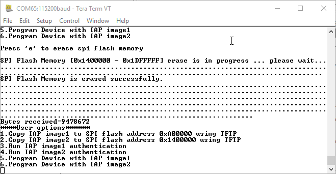
The images are transferred successfully to external SPI Flash using TFTP. The firmware application takes care of the external SPI Flash programming with SPI directory as shown in the following figure.
