
9.6.10.1 Single Device Programming
When devices are joined together in a JTAG chain, all of their Instruction Registers (IR) and Data Registers (DR) are put in a long shift register from TDI to TDO. The IR length defers from device to device and the DR length depends on the instruction that shifts into the instruction register.
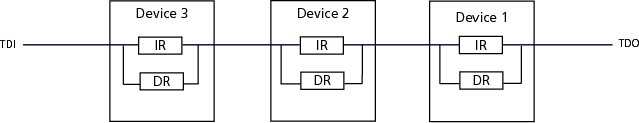
When the bypass instruction is shifted into Device 1 and Device 3, the TDI and TDO of the two devices are connected to the 1-bit bypass register at the Shift-DR state. To correctly shift the data in and data out of Device 2's register, you need to shift one bit of data before and after Device 2's data.
The number of bits you need to shift into the data register for Device 1 is the pre-DR length and the number of bits we need to shift into the data register for Device 3 is the post-DR length. With the IR and DR length information, you can shift instructions and data into Device 2 with the correct registration.
To create the JTAG chain:
- Connect the TCK and TMS from the programmer to all of the devices.
- Connect the programmer’s TDI pin to the TDI pin of device 3.
- For all devices in the chain, connect the TDO output of one device to the TDI input of the next device.
- Connect the TDO output of the last device to the programmer’s TDO input.
The order of devices in the chain is set by the connections of TDI to TDO. The ChainBuilder software takes the order of the devices in a chain and their IR lengths and adds the pre-IR, post-IR, pre-DR, and post-DR padding bits in the device you want to program, which properly aligns the instructions and data within the IR and DR of the devices.
If you do not use the ChainBuilder software, the FlashPro software tries to find the pre-IR, post IR, pre-DR, and post-DR values during the Analyze Chain operation.
For more information, see the ProASICPLUS and ProASIC programming introduction section. To find out how to set the IR length, see the Chain Settings. section.