
Timing Diagram (No Pipeline Functions)
(Ask a Question)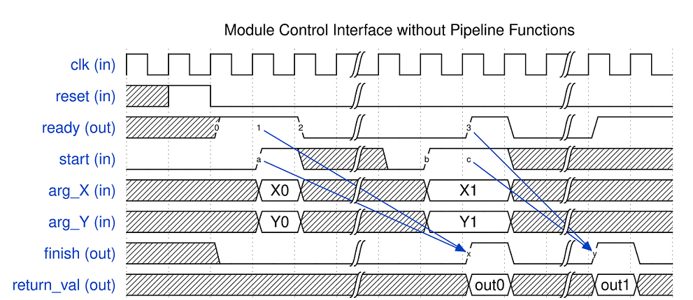
The timing diagram above illustrates the behaviour of the module control interface when the generated circuit contains no pipelined circuits.
- First, the ready signal comes out high after reset (label 0).When the start signal becomes high at the next cycle (label a), the handshaking between ready and start (label 1 & a) occurs and the top-level module starts running.
-
- Notice that at the same time as the start signal is asserted (label a), the argument inputs (i.e., arg_X and arg_Y) should also be provided to the top-level module. The scalar argument inputs are sampled by the top-level module when the handshaking occurs and will be used as the input for the current invocation.
- Then the ready signal goes to low at the next cycle (label 2) to indicate the top-level module cannot accept a new invocation.
- When the ready signal is low, the start signal is ignored by the top-level module. For example, the start signal becomes high at label b. The ready signal from the top-level module is still low at this cycle and hence a new function invocation won't be started yet.
- At label x, when the previous invocation finishes, the top-level module sets finish signal high for one clock cycle. In this clock cycle, the return value of the top-level function is available on the return_val port.
- Meanwhile, the ready signal becomes high as the previous invocation finishes (label 3). A new handshaking with start occurs (label 3 & c), then the top-level function starts the second invocation and finishes at label y.