
Timing Diagram (Pipeline Functions)
(Ask a Question)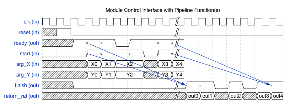
The timing diagram above illustrates the module control interface when the generated circuit contains pipelined function(s). In this case, the SmartHLS circuit can overlap the execution of multiple invocations, by starting a new invocation with a new set of inputs before previous invocations have finished.
- There are a total of five invocations (or five ready and start handshakings, label 0-4 & a-e). As shown in the diagram, the new invocations can start without waiting for the prior invocations to finish.
- Although the SmartHLS circuit can process multiple invocations in parallel, there are times when the SmartHLS circuit cannot start a new invocation. Such case can happen when the pipeline initiation internal is not 1 (i.e., the SmartHLS circuit cannot start a new invocation every clock cycle), or when the circuit is stalled waiting for resource/data to become available (e.g., waiting to read from an input FIFO). When the SmartHLS circuit can not start a new invocation, the ready signal will be set to low.
- For example, the ready signal is low for one cycle before label 2, postponing the start of the third invocation until the ready signal is back to high at label 2 & c.
- The external logic of the SmartHLS circuit can also lower the start signal to delay the start of a new invocation, as shown in the cycle before label d.
- The invocations are always finished in the same order as they started. That is, the handshakings at label 0 & a, 1 & b, 2 & c, 3 & d, 4 & e, are corresponding to the completion at label o, p, q, r, s, respectively.