
24.4.4.8.2 SDR Error Detection and Recovery Methods
There are three error types for SDR transfers and their recovery methods, as listed in Table 24-16.
| Error Type | Description | Error Detection Method | Error Recovery Method |
|---|---|---|---|
|
CE0 |
Transaction after sending CCC |
Detects illegally formatted CCCs. |
Stop the transmission, then send STOP and retry the transmission. |
|
CE2 |
No response to broadcast address (7'h7E) |
Controller detects NACK after broadcast address (7'h7E) transmission. |
Upon detection of NACK, the controller transmits the HDR Exit Pattern followed by STOP. |
|
CE3 |
Failed controller handoff |
Active Controller detects that the new controller does not drive the bus after handoff. |
Active Controller regains the controller role and drives the bus to assert its controller role. |
Error Type CE0
If the controller detects an illegally formatted CCC, then the controller stops the transmission, sends STOP, and tries the transmission again.
An example of an illegally formatted CCC is when the controller receives just one byte from the target in a GETMWL CCC code. The controller expects two bytes and does not decode the CCC as it is transparent for the application. The controller always initiates the CCC transfer and expects the number of bytes as mentioned in the DATA_LENGTH field of the Transfer Argument. If the target terminates earlier than the DATA_LENGTH expected by the controller, the controller represents it in the DATA_LENGTH of the RESPONSE.
The application has to decode this information through the RESPONSE of the CCC transfer and can re-issue the same command in the COMMAND_QUEUE for re-transmission.
Error Type CE2
If the controller does not receive an ACK for a transmitted broadcast address (7'h7E), then it transmits the HDR Exit Pattern followed by STOP. The controller always generates STOP upon receiving a NACK for the broadcast address (7'h7E) and enters the HALT state. This can be detected through the I3CxINTSTA[TRANSERR].
Error Type CE3
After the Active Controller prepares for the handoff, the Active Controller issues a GETACCCR CCC followed by a STOP. Following the STOP and Bus Available Condition, the selected secondary controller assumes the role of the Active Controller and takes control of the I3C Bus. The former Active Controller should monitor the I3C Bus to ensure that the new Active Controller asserts its Controller Role. After the handoff procedure, the new Active Controller (NCR) issues a START to assert its Controller Role within 100μs or the time interval indicated by its Activity State (as reported by the GETMXDS CCC with optional Defining Byte), whichever is greater. If the new Active Controller does not issue a START, then it responds to SDA being pulled Low by pulling SCL Low; this is a START, and the new Active Controller may follow it with any valid Bus activity that is sufficient to assert the Controller Role. If the new controller does not respond by pulling SCL Low within that period, then the former Active Controller pulls SCL Low to regain the Bus Controller Role.
Defining Byte Support
The Defining Byte Support feature is an extended feature of the existing CCC transfers model. The Defining Byte is included after the CCC Code and before the payload (in broadcast CCCs)/Restart (Directed CCCs) to indicate an extended capability or an action associated with the CCC. The Defining Byte is supported for both Broadcast and Directed SDR CCC transfers. In both cases, the Defining Byte is included after the CCC Code byte as a sub-command before the Payload. Figure 24-23 and Figure 24-24 describe the placement of the Defining Byte in Broadcast CCC and Directed CCC transfers, respectively.

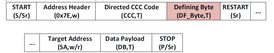
The Defining Byte is enabled for Broadcast or Directed SDR CCC transfers by setting the ‘Defining Byte Present (DBP)’ bit in the Transfer Command, and the Defining Byte value is captured from the ‘Defining Byte (DB)’ field of the Transfer Argument or Short Data Argument.