6.3.5.1 Set Up the Hardware
To set up the hardware for this example:
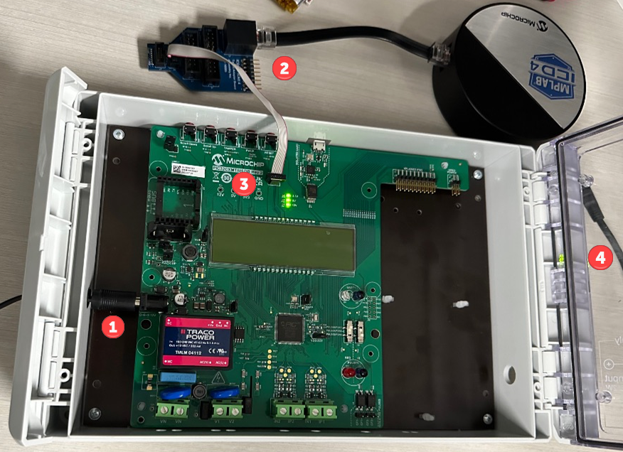
- Apply power to the PIC32CXMTSH-DB evaluation board. If the board is in a safety case, push the power plug through the hole in the case and into the power connector.
- Depending on debug tool used:
- PICkit 4: Connect the debug tool to the 8-pin SIL connector on the ICD 4/PICkit 4 Target Adapter Board. Then attach one end of the 10-pin mini ribbon cable to the adapter board JTAG/SWD connector.
- MPLAB ICD 4: Connect the debug tool via the RJ-45 cable to the ICSP connector on the ICD 4/PICkit 4 Target Adapter Board. Then attach one end of the 10-pin mini ribbon cable to the adapter board JTAG/SWD connector.
- MPLAB ICE 4: Connect the debug tool via the high-speed 40-pin cable to the ICE 4 JTAG Adapter board. Then attach one end of the 10-pin mini ribbon cable to the 10-pin connector (J3) on the top of the adapter board.
- Connect the other end of the 10-pin mini ribbon cable to the SWD/JTAG 10-pin connector on the evaluation board.
- Connect the debug tool to the PC and apply power (if separate from communications connection.)