
2.3.2 Instantiating AXI Interconnect Bus IP
(Ask a Question)The AXI interconnect bus must be configured to connect the Mi-V core with memory. Also, the AXI4Interconnect is needed for converting the Mi-V processor’s AXI4 32-bit data to the DDR3 AXI4 64-bit data, and also for bridging the Mi-V processor’s AXI4 clock rate of 83.3 MHz to the DDR3 AXI4 clock rate of 166.66 MHz.
- From the Catalog, drag the CoreAXI4Interconnect IP core to SmartDesign.
- In the Create Component dialog box, enter COREAXI4INTERCONNECT_C0 as the component name, and click OK. The Configurator window opens.
- Under the Configuration tab, in the Bus Configuration section, configure the COREAXI4INTERCONNECT IP to have one slave with an ID width of 1, as shown in the following figure. Leave the rest as defaults.
Figure 2-6. CoreAXI4Interconnect Configurator – Bus Configuration Section 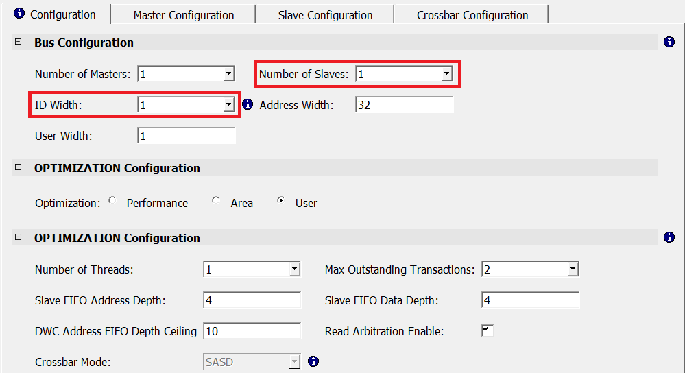
- In the Master
Configuration tab, retain the following Master0 configuration
default settings:
- M0 Type: AXI4
- M0 Data Width: 32 bits
- M0 DWC Data FIFO Depth: 16
- M0 Register Slice: Selected
The following figure shows the Master0 configuration.Figure 2-7. CoreAXI4Interconnect - Master0 Configuration 
- In the Slave Configuration tab, configure the Slave0 port as follows:
- S0 SLAVE Start Address (Lower 32 bits): 0x80010000
- S0 SLAVE End Address (Lower 32 bits): 0x8FFFFFFF
- S0 Clock Domain Crossing: Enabled
- Leave the rest as defaults
Figure 2-8. CoreAXI4Interconnect Configurator – Slave0 Configuration 6. 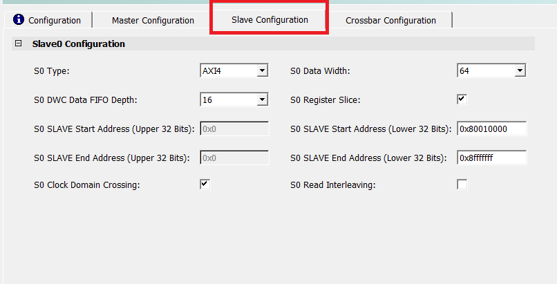
- In the Crossbar Configuration tab, ensure that the following options are set:
- Under Enable Master Write Access, M0 access to S0 is enabled, and under Enable Master Read Access, M0 access to S0 is enabled.
- Leave the rest as defaults.
Figure 2-9. Crossbar Configuration and Enabling Master Write Access Settings 