
1.3.9 Voltage Monitor
The Voltage Monitor contains a 2-channel analog multiplexer that allows an incoming analog signal to be routed directly to the analog-to-digital converter, or allows the signal to be routed to a prescaler circuit before being sent to the ADC.
For more information on the Digital filtering factor, Acquisition time, and Comparison Flag Specifications, refer to the Configuring Current, Differential Voltage, Temperature, and Voltage Peripherals.
Use Prescaler or Direct Analog
Each Analog channel has an associated prescaler circuit which can prescale the input signal to a appropriate value supported by the ADC. Using the prescaler circuit imposes certain requirements on the acquisition time of the peripheral. The two radio buttons in front of the multiplexer determine if the Voltage monitor uses prescaling or not.
If the input value is less than the ADC reference voltage and high accuracy is critical for the application, choose the direct analog path. The prescaler circuit could introduce potential gain errors or offset errors. If resolution is more important than accuracy for input voltage ranges lower than the ADC reference voltage, choose the prescaler path.
The prescaler logic of the AB has a settling time of 10 s (max). It is an application-dependent setting and must be accounted for by you via the acquisition and hold time for each channel. A recommended default value is inserted by ASB when configuring a new Voltage Monitor but it may be reduced with the possible reduction in sampling accuracy.
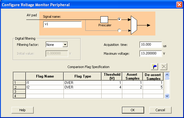
Maximum Voltage
The maximum anticipated voltage measured by this Voltage Monitor peripheral pad. The range is -10.5V to +16V (the voltage range is NOT bipolar). The ADC is capable of measuring a voltage range of 0 - Vref. For the Internal voltage reference, this value is 2.56V. ASB automatically configures the prescaler in the AB Analog Block for this peripheral to maximize the available voltage range.
For example, if an OVER -3V flag was configured, the flag would assert whenever the input voltage is -1, -2, up to the threshold value. The flag would deassert when the value is -4, -5, etc.