
14.12 Carry Chain Macros
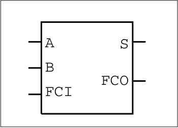
ADD1
This component is supported by Accelerator families.

- Function: 1 Bit Adder
- Input: A, B, FCI
- Output: S, FCO
| A | B | FCI | S | FCO |
|---|---|---|---|---|
| 0 | 0 | 0 | 0 | 0 |
| 0 | 0 | 1 | 1 | 0 |
| 0 | 1 | 0 | 1 | 0 |
| 0 | 1 | 1 | 0 | 1 |
| 1 | 0 | 0 | 1 | 0 |
| 1 | 0 | 1 | 0 | 1 |
| 1 | 1 | 0 | 0 | 1 |
| 1 | 1 | 1 | 1 | 1 |
| Family | COMB |
|---|---|
| All listed | 1 |
SUB1
This component is supported by Accelerator families.
- Function: 1 Bit Subtractor
- Input: A, B, FCI
- Output: S, FCO
| A | B | FCI | S | FCO |
|---|---|---|---|---|
| 0 | 0 | 0 | 1 | 0 |
| 0 | 0 | 1 | 0 | 1 |
| 0 | 1 | 0 | 0 | 0 |
| 0 | 1 | 1 | 1 | 0 |
| 1 | 0 | 0 | 1 | 0 |
| 1 | 0 | 1 | 1 | 1 |
| 1 | 1 | 0 | 1 | 0 |
| 1 | 1 | 1 | 0 | 1 |
| Family | Comb |
|---|---|
| All listed | 1 |
ADDSUB1
This component is supported by Accelerator families.
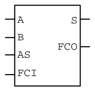
- Function: 1 Bit Add Sub macro
- Input: AS, B, A, FCI
- Output: S, FCO
| AS | B | A | FCI | S | FCO |
|---|---|---|---|---|---|
| 0 | 0 | 0 | 0 | 1 | 0 |
| 0 | 0 | 0 | 1 | 0 | 1 |
| 0 | 0 | 1 | 0 | 0 | 1 |
| 0 | 0 | 1 | 1 | 1 | 1 |
| 0 | 1 | 0 | 0 | 0 | 0 |
| 0 | 1 | 0 | 1 | 1 | 0 |
| 0 | 1 | 1 | 0 | 1 | 0 |
| 0 | 1 | 1 | 1 | 0 | 1 |
| 1 | 0 | 0 | 0 | 0 | 0 |
| 1 | 0 | 0 | 1 | 1 | 0 |
| 1 | 0 | 1 | 0 | 1 | 0 |
| 1 | 0 | 1 | 1 | 0 | 1 |
| 1 | 1 | 0 | 0 | 1 | 0 |
| 1 | 1 | 0 | 1 | 0 | 1 |
| 1 | 1 | 1 | 0 | 0 | 1 |
| 1 | 1 | 1 | 1 | 1 | 1 |
| Family | Comb |
|---|---|
| All listed | 2 |
MULT1
This component is supported by Accelerator families.
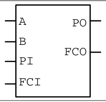
- Function: 1 Bit Multiplier
- Input: A, B, PI, FCI
- Output: PO, FCO
| A | B | PI | FCI | PO | FCO |
|---|---|---|---|---|---|
| 0 | 0 | 0 | 0 | 0 | 0 |
| 0 | 0 | 0 | 1 | 1 | 0 |
| 0 | 0 | 1 | 0 | 1 | 0 |
| 0 | 0 | 1 | 1 | 0 | 1 |
| 0 | 1 | 0 | 0 | 0 | 0 |
| 0 | 1 | 0 | 1 | 1 | 0 |
| 0 | 1 | 1 | 0 | 1 | 0 |
| 0 | 1 | 1 | 1 | 0 | 1 |
| 1 | 0 | 0 | 0 | 0 | 0 |
| 1 | 0 | 0 | 1 | 1 | 0 |
| 1 | 0 | 1 | 0 | 1 | 0 |
| 1 | 0 | 1 | 1 | 0 | 1 |
| 1 | 1 | 0 | 0 | 1 | 0 |
| 1 | 1 | 0 | 1 | 0 | 1 |
| 1 | 1 | 1 | 0 | 0 | 1 |
| 1 | 1 | 1 | 1 | 1 | 1 |
| Family | Comb |
|---|---|
| All listed | 1 |
ARCNTECP1
This component is supported by Accelerator families.

- Function: 1 Bit counter
- Input: FCI, CLK, PRE, CLR, UD
- Output: Q, FCO
| FCI | UD | PRE | CLR | E | CLK | FCO | Qn+1 |
|---|---|---|---|---|---|---|---|
| X | X | 0 | X | X | X | X | 1 |
| X | X | 1 | 0 | X | X | X | 0 |
| X | X | 1 | 1 | 1 | X | X | Qn |
| See Equations | See Equations | 1 | 1 | 0 | ↑ | See Equations | See Equations |
Qn+1 = FCI ∧ UD ∧ Qn
FCO = FCI.UD + FCI.Qn + UD.Qn
| Family | Comb | Seq |
|---|---|---|
| All listed | 1 | 1 |
AFCNTECP1
This component is supported by Accelerator families.

- Function: 1 Bit counter
- Input: FCI, CLK, PRE, CLR, UD
- Output: Q, FCO
| FCI | UD | PRE | CLR | E | CLK | FCO | Qn+1 |
|---|---|---|---|---|---|---|---|
| X | X | 0 | X | X | X | X | 1 |
| X | X | 1 | 0 | X | X | X | 0 |
| X | X | 1 | 1 | 1 | X | X | Qn |
| See Equations | See Equations | 1 | 1 | 0 | ↓ | See Equations | See Equations |
Qn+1 = FCI ∧ UD ∧ Qn
FCO = FCI.UD + FCI.Qn + UD.Qn
| Family | Comb | Seq |
|---|---|---|
| All listed | 1 | 1 |
SRCNTECP1
This component is supported by Accelerator families.

- Function: 1 Bit counter
- Input: FCI, CLK, PRE, CLR, UD
- Output: Q, FCO
| FCI | UD | PRE | CLR | E | CLK | FCO | Qn+1 |
|---|---|---|---|---|---|---|---|
| X | X | 0 | X | X | X | X | 1 |
| X | X | 1 | 0 | X | X | X | 0 |
| X | X | 1 | 1 | 1 | X | X | Qn |
| See Equations | See Equations | 1 | 1 | 0 | ↑ | See Equations | See Equations |
Qn+1 = FCI ∧ !UD ∧ Qn
FCO = FCI.!UD + FCI.Qn + !UD.Qn
| Family | Comb | Seq |
|---|---|---|
| All listed | 1 | 1 |
SFCNTECP1
This component is supported by Accelerator families.

- Function: 1 Bit counter
- Input: FCI, CLK, PRE, CLR, UD
- Output: Q, FCO
| FCI | UD | PRE | CLR | E | CLK | FCO | Qn+1 |
|---|---|---|---|---|---|---|---|
| X | X | 0 | X | X | X | X | 1 |
| X | X | 1 | 0 | X | X | X | 0 |
| X | X | 1 | 1 | 1 | X | X | Qn |
| See Equations | See Equations | 1 | 1 | 0 | ↓ | See Equations | See Equations |
Qn+1 = FCI ∧ !UD ∧ Qn
FCO = FCI.!UD + FCI.Qn + !UD.Qn
| Family | Comb | Seq |
|---|---|---|
| All listed | 1 | 1 |
ARCNTELDCP1
This component is supported by Accelerator families.

- Function: 1 Bit counter
- Input: FCI, CLK, PRE, CLR, E, LD, D, and UD
- Output: Q, FCO
| FCI | UD | PRE | CLR | E | LD | D | CLK | FCO | Qn+1 |
|---|---|---|---|---|---|---|---|---|---|
| X | X | 0 | X | X | X | X | X | X | 1 |
| X | X | 1 | 0 | X | X | X | X | X | 0 |
| X | X | 1 | 1 | 1 | X | X | X | X | Qn |
| X | X | 1 | 1 | 0 | 1 | 0 | ↑ | X | 0 |
| X | X | 1 | 1 | 0 | 1 | 1 | ↑ | X | 1 |
| See Equations | See Equations | 1 | 1 | 0 | 0 | X | ↑ | See Equations | See Equations |
Qn+1 = FCI ∧ UD ∧ Qn
FCO = FCI.UD + FCI.Qn + UD.Qn
| Family | Comb | Seq |
|---|---|---|
| All listed | 2 | 1 |
AFCNTELDCP1
This component is supported by Accelerator families.

- Function: 1 Bit counter
- Input: FCI, CLK, PRE, CLR, E, LD, D, and UD
- Output: Q, FCO
| FCI | UD | PRE | CLR | E | LD | D | CLK | FCO | Qn+1 |
|---|---|---|---|---|---|---|---|---|---|
| X | X | 0 | X | X | X | X | X | X | 1 |
| X | X | 1 | 0 | X | X | X | X | X | 0 |
| X | X | 1 | 1 | 1 | X | X | X | X | Qn |
| X | X | 1 | 1 | 0 | 1 | 0 | ↓ | X | 0 |
| X | X | 1 | 1 | 0 | 1 | 1 | ↓ | X | 1 |
| See Equations | See Equations | 1 | 1 | 0 | 0 | X | ↓ | See Equations | See Equations |
Qn+1 = FCI ∧ UD ∧ Qn
FCO = FCI.UD + FCI.Qn + UD.Qn
| Family | Comb | Seq |
|---|---|---|
| All listed | 2 | 1 |
SRCNTELDCP1
This component is supported by Accelerator families.

- Function: 1 Bit counter
- Input: FCI, CLK, PRE, CLR, E, LD, D, and UD
- Output: Q, FCO
| FCI | UD | PRE | CLR | E | LD | D | CLK | FCO | Qn+1 |
|---|---|---|---|---|---|---|---|---|---|
| X | X | 0 | X | X | X | X | X | X | 1 |
| X | X | 1 | 0 | X | X | X | X | X | 0 |
| X | X | 1 | 1 | 1 | X | X | X | X | Qn |
| X | X | 1 | 1 | 0 | 1 | 0 | ↑ | X | 0 |
| X | X | 1 | 1 | 0 | 1 | 1 | ↑ | X | 1 |
| See Equations | See Equations | 1 | 1 | 0 | 0 | X | ↑ | See Equations | See Equations |
Qn+1 = FCI ∧ !UD ∧ Qn
FCO = FCI.!UD + FCI.Qn + !UD.Qn
| Family | Comb | Seq |
|---|---|---|
| All listed | 2 | 1 |
SFCNTELDCP1
This component is supported by Accelerator families.

- Function: 1 Bit counter
- Input: FCI, CLK, PRE, CLR, E, LD, D, and UD
- Output: Q, FCO
| FCI | UD | PRE | CLR | E | LD | D | CLK | FCO | Qn+1 |
|---|---|---|---|---|---|---|---|---|---|
| X | X | 0 | X | X | X | X | X | X | 1 |
| X | X | 1 | 0 | X | X | X | X | X | 0 |
| X | X | 1 | 1 | 1 | X | X | X | X | Qn |
| X | X | 1 | 1 | 0 | 1 | 0 | ↓ | X | 0 |
| X | X | 1 | 1 | 0 | 1 | 1 | ↓ | X | 1 |
| See Equations | See Equations | 1 | 1 | 0 | 0 | X | ↓ | See Equations | See Equations |
Qn+1 = FCI ∧ !UD ∧ Qn
FCO = FCI.!UD + FCI.Qn + !UD.Qn
| Family | Comb | Seq |
|---|---|---|
| All listed | 2 | 1 |
FCEND_BUFF
This component is supported by Accelerator families.

- Function: Buffer, driven by the FCO pin of the last macro in the Carry-Chain
- Input: A
- Output: Y
| A | Y |
|---|---|
| 0 | 0 |
| 1 | 1 |
| Family | Seq | COMB |
|---|---|---|
| All | — | 1 |
FCEND_INV
This component is supported by Accelerator families.

- Function: Inverter with Active Low output; driven by the FCO pin of the last macro in the Carry-Chain
- Input: A
- Output: Y
| A | Y |
|---|---|
| 0 | 1 |
| 1 | 0 |
| Family | Seq | COMB |
|---|---|---|
| All | — | 1 |
FCINIT_BUFF
This component is supported by Accelerator families.

- Function: Buffer, used to initialize the FCI pin of the first macro in the Carry-Chain with an external signal
- Input: A
- Output: Y
| A | Y |
|---|---|
| 0 | 0 |
| 1 | 1 |
| Family | Seq | COMB |
|---|---|---|
| All | — | 1 |
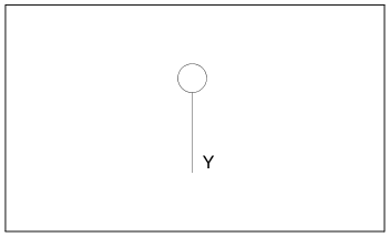
FCINIT_GND
This component is supported by Accelerator families.

- Function: Ground; used to initialize the FCI pin of the first macro in the Carry-Chain to GND
- Input:
- Output: Y
FCINIT_INV
This component is supported by Accelerator families.
- Function: Inverter with Active Low output; used to initialize the FCI pin of the first macro in the Carry-Chain with an external signal
- Input: A
- Output: Y
| A | Y |
|---|---|
| 0 | 1 |
| 1 | 0 |
| Family | Seq | COMB |
|---|---|---|
| All | — | 1 |
FCINIT_VCC
This component is supported by Accelerator families.
- Function: Power; used to initialize the FCI pin of the first macro in the Carry-Chain to VCC
- Input: A
- Output: Y