
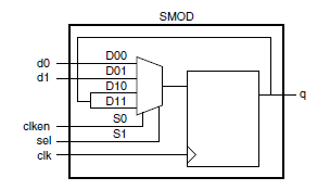
11.4.3.2 Clock Enabled
The clock enabled register uses a 2:1 multiplexor with output feedback, which uses some of the SMOD multiplexor. The following example shows how to share a clock enabled register with the input logic.
VHDL
-- register with active low async reset, shared with a 2-to-1
-- mux, and an active high clock enable.
library ieee;
use ieee.std_logic_1164.all;
entity dfm_clken is
PORT (d0, d1: in std_logic;
clk, reset, clken, sel: in std_logic;
q: out std_logic;
end dfm_clken;
architecture behav of dfm_clken is
signal tmp_sel: std_logic_vector(1 downto 0);
signal q_tmp: std_logic;
begin
process (clk, reset) begin
tmp_sel <= clken & sel;
if (reset = '0') then
q_tmp <= '0';
elsif (clk'event and clk ='1') then
case tmp_sel is
when "00" => q_tmp <= d0;
when "01" => q_tmp <= d1;
when "10" => q_tmp <= q_tmp;
when "11" => q_tmp <= q_tmp;
when others => q_tmp <= q_tmp;
end case;
end if;
end process;
q <= q_tmp;
end behav;
Verilog
/* register with asynchronous reset, clock enable,
shared with a 2-to-1 mux */
module dfm_clken (d0, d1, clk, reset, clken, sel, q);
input d0, d1;
input sel;
input clk, reset, clken;
output q;
reg q;
always @ (posedge clk or negedge reset)
begin
if (!reset)
q = 1'b0;
else
case ({clken, sel})
2'b00: q = d0;
2'b01: q = d1;
2'b10: q = q;
2'b11: q = q;
endcase
end
endmodule