24.4.4.4.3 IBI Status and Data Structure
When an In-Band Interrupt (IBI) request is received, the status of the received IBI is placed into the IBI queue (I3CxIBIQUE) with the following data structure:
| Bits | Field Name | Access Type | Reset Value | Description |
|---|---|---|---|---|
|
31 |
IBI_STS |
R |
0x0 |
IBI Status Indicates the status of the response returned for the received IBI. 1’b0: The received IBI is responded to with an ACK. Any non-zero value of the DATA_LEN field indicates the presence of a data payload for the ACK’d IBI. 1’b1: The received IBI is responded to with a NACK. An auto-disable CCC command is issued if the received IBI address is valid and matches the DAT entry. If an IBI is received from an unknown address (not a valid entry in DAT), the IBI_STS is set to 1. |
|
30 |
ERROR |
R |
0x0 |
Error Indicates that during the IBI Auto command, an error is encountered
and the data from the target device is partially or fully discarded.
The following errors are detected:
1’b1: Error. Error encountered during the IBI Auto command phase. |
|
29:26 |
RESV |
R |
0x0 | — |
|
25 |
TS |
R |
0x0 |
IBI Timestamp Present indicates whether a timestamp is available for the IBI. Values:
|
|
24 |
LAST_STATUS |
R |
0x0 |
Last Status When set, this indicates that this status is the last for the received IBI. If the payload of the received SIR exceeds the programmed IBI data threshold, then the Controller splits the IBI payload into multiple chunks of IBI_DATA_THLD size (max), which includes the timestamp bytes if enabled. |
|
23:16 |
RESV |
R |
8’h00 |
Reserved |
|
15:8 |
IBI_ID |
R |
8’h00 |
IBI identifier This field indicates the target address byte along with the RnW bit received from the target device. |
|
7:0 |
DATA_LENGTH |
R |
8’h00 |
IBI Data Length Number of data bytes received from the target device either along with the SIR or with the auto-command (read). The data length is limited by QUEUE_THLD_CTRL[IBI_DATA_THLD]. |
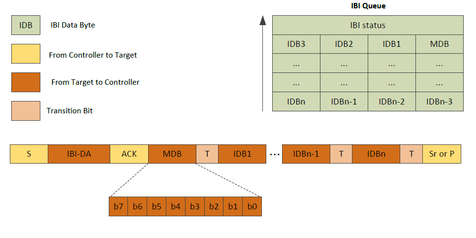
The Controller receives the bytes in the same order as on the bus and places the first byte received in the Least Significant Byte (LSB) position, and the following bytes in the LSB + 1 location, until all four bytes of a word are received in the IBI Queue. The data is always preceded by IBI status and indicates the number of valid IBI data bytes as shown in Figure 24-13.