
9.18.3 FlashPro® Lite
For FlashPro® Lite, the existing 26-pin connector is shown in the figure below.
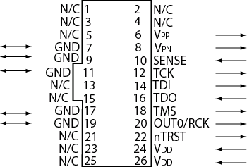
The appropriate SAMTEC micro connector target cable for this is: Samtec FFSD-13-D-12.00-01-N.
The 12 inch cable is specified. This is likely to be more than enough to connect to the board and reducing the inductance will help compared with 18 inches, which is supplied by the default with FlashPro Lite.
See the following table for a description of the signals.
Signal | Description |
|---|---|
VDDP | VDD supply for logic I/O pads |
VDDL | VDD supply for core |
VPP | Positive programming supply (+16.5V) |
VPN | Negative programming supply(-13.8V) |
GND | Signal reference |
SENSE | Input from target board to programmer to indicate connection to ground |
TCK | JTAG clock |
|
TDI |
JTAG data input to device |
|
TDO |
JTAG data output from device |
|
TMS |
JTAG mode select |
|
nTRST |
Programmable output pin may be set to off, toggle, low, or high level |
|
RCK/OUT0 |
Programmable output pin may be set to off, toggle, low, or high level |
|
N/C |
Programmer does not connect to this pin |
Some designers of high-integrity boards (military and avionic) may arrange their boards so that TRST is tied to ground via a weak pull-down resistor. The purpose of this is to hold the JTAG state-machine in a reset state by default, so that even with TCK oscillating, some sudden ion bombardment or other electrical even will not suddenly throw the JTAG state-machine into an unknown state. If your design also uses a weak pull-down resistor on TRST on your board, then enabling the "Drive TRST" flag will be required to force the JTAG state-machine out of reset to permit programming to take place. With most boards, there is no need to select this flag.