
9.18.2 FlashPro®3
The FlashPro®3 output is supplied via a connector to which a detachable 10-pin cable is fitted. The connector on the FlashPro3 unit is a 2x5, RA male Header connector, which is manufactured by AMP and has a manufacturer’s part number of 103310-1. This is a standard 2x5, 0.1 pitch connector which is keyed. Use the 10 pin right-angle header, AMP P/N 103310-1 (DigiKey P/N A26285-ND) for FlashPro4/3/3X and use the 10 pin straight header, AMP P/N 103308-1 (DigiKey P/N A26267-ND) for the straight version.
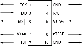
The table below shows a description of the signals.
| Signal | Description |
|---|---|
| VPUMP | 3.3V Programming voltage. |
| GND | Signal reference. |
| TCK | JTAG clock. |
| TDI | JTAG data input to device. |
| TDO | JTAG data output from device. |
| TMS | JTAG mode select. |
| nTRST | Programmable output pin may be set to off, toggle, low, or high level. |
| VJTAG | Reference voltage from the target board. |
| N/C | Programmer does not connect to this pin. |
Some designers of high-integrity boards (military and avionic) may arrange their boards so that TRST is tied to ground via a weak pull-down resistor. The purpose of this is to hold the JTAG state-machine in a reset state by default, so that even with TCK oscillating, some sudden ion bombardment or other electrical even will not suddenly throw the JTAG state-machine into an unknown state. If your design also uses a weak pull-down resistor on TRST on your board, then enabling the “Drive TRST” flag will be required to force the JTAG state-machine out of reset to permit programming to take place. With most boards, there is no need to select this flag.