
9.18.4 FlashPro®
For FlashPro®, you can use the same 26-pin target cable you used for FlashPro® Lite, but the connections are shown in the figure.
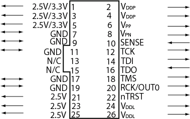
The table below shows the signal pin descriptions for FlashPro.
Signal | Description |
|---|---|
VDDP | VDD supply for logic I/O pads |
VDDL | VDD supply for core |
VPP | Positive programming supply (+16.5 V) |
VPN | Negative programming supply (-13.8 V) |
GND | Signal reference |
SENSE | Input from target board to programmer to indicate connection to ground |
TCK | JTAG clock |
TDI | JTAG data input to device |
TDO | JTAG data output from device |
TMS | JTAG mode select |
nTRST | Programmable output pin may be set to off, toggle, low, or high level |
RCK/OUT0 | Programmable output pin may be set to off, toggle, low, or high level |
2.5V, 2.5V/3.3V, N/C | Programmer does not connect to these pins |
Some designers of high-integrity boards (military and avionic) may arrange their boards so that TRST is tied to ground via a weak pull-down resistor. The purpose of this is to hold the JTAG state-machine in a reset state by default, so that even with TCK oscillating, some sudden ion bombardment or other electrical even will not suddenly throw the JTAG state-machine into an unknown state. If your design also uses a weak pull-down resistor on TRST on your board, then enabling the "Drive TRST" flag will be required to force the JTAG state-machine out of reset to permit programming to take place. With most boards, there is no need to select this flag.