1.3.7.1 RTC Signals
All signals are active high.
| Name | Type | Direction |
|---|---|---|
| RTCCLK | INPUT | RTC Clock; must be driven by the XTLOUT of the XTLOSC macro |
| RTCXTLSEL | OUTPUT | Crystal Oscillator select; must be connected to the XTLSEL on the XTLOSC macro |
| RTCXTLMODE[1:0] | OUTPUT | Crystal Oscillator mode select; must be connected to RTCXTLMODE on the XTLOSC macro |
| RTCMATCH | OUTPUT | Match signal when match value reached |
| RTCPSMMATCH | OUTPUT | Match signal when match value reached; must be connected to RTCMATCH of VRPSM macro. Exposed only if "Export Match signal for Voltage Regulator Power Supply Monitor" is enabled. |
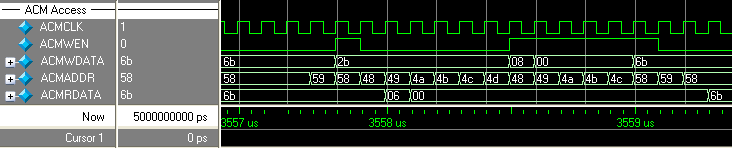
The following timing diagram displays accessing the ACM for the RTC values. In the diagram, the RTC counter is disabled. Then, the RTC match register is read and finally the match register is overwritten with a new value. The RTC is then re-enabled.