
5.24 Reference
SmartDesign Menu
Command | Icon | Function |
Show Canvas View |
| Displays the Canvas |
Show Grid View |
| Displays the Grid |
Show Schematic View |
| Displays the Schematic Viewer |
Show Memory Map / Data Sheet | Displays the datasheet for the design | |
Check Design Rules |
| Runs the Design Rules Check |
Generate Design |
| Generates your SmartDesign component |
Auto Connect |
| Auto-connects instances |
Add Port | Adds a port to the top of the SmartDesign component |
Command | Icon | Function |
Auto-Arrange Instances |
| Auto-arranges the Canvas location of the instances on your Canvas; note that the Canvas location of the instances is a representation and not the actual layout. |
Auto-Arrange Connections |
| Auto-arranges the Canvas location of the connections on your Canvas; note that the Canvas location of the instances is a representation and not the actual layout |
Command | Icon | Function |
Nets | Shows/hides the nets on the Canvas | |
Ruler | Shows/hides the ruler at the edges of your Canvas | |
Grid Points | Shows/hides grid points on your Canvas | |
Page Bounds | Shows/hides the page boundaries on your Canvas |
Command | Function |
Hide All Connected Ports | Hides all connected ports in the current grid |
Fit All Columns to Data | Fits the column size to the data in the column |
Reset Instance [or Net] View to Default | Resets the grid layout for the current grid |
Show All Rows | Shows all rows in the Display Panel |
Show All Instance Columns | Shows all instance columns in the Connection Panel |
Show All Rows and Columns | Shows all rows and columns in the Display Panel |
Attribute Column | Shows/hides the Attribute column in the Connection Panel |
Top Level Column | Shows/hides the Top Level column in the Connection Panel |
Fields | Shows/hides the selected field in the Display Panel |
Command | Icon | Function |
Command | Icon | Function |
Go To First Page |
| Goes to first page in Schematic View (when using page splitting) |
Go To Previous Page |
| Goes to previous page in Schematic View (when using page splitting) |
Go To Next Page |
| Goes to next page in Schematic View (when using page splitting) |
Go To Last Page |
| Goes to last page in Schematic View (when using page splitting) |
Allow Page Splitting | Allows page splitting; useful when you have a large schematic | |
Fit to Page | Fits the content to a single page |
Term | Description |
BIF | Abbreviation for bus interface. |
bus | An array of scalar ports or pins, where all scalars have a common base name and have unique indexes in the bus. |
Bus Definition | Defines the signals that comprise a bus interface. Includes which signals are present on a master, slave, or system interface, signal direction, width, default value, etc. A bus definition is not specific to a logic or design component but is a type or protocol. |
Bus Interface | Logical grouping of ports or pins that represent a single functional purpose. May contain both input and output, scalars or busses. A bus interface is a specific mapping of a bus definition onto a component instance. |
Bus Interface Net | A connection between 2 or more compatible bus interfaces. |
Canvas | Block diagram, connections represent data flow; enables you to connect instances of components in your design. |
Term | Description |
Component | Design element with a specific functionality that is used as a building block to create a SmartDesign core. A component can be an HDL module, non-IP core generated from the Catalog, SmartDesign core, Designer Block, CoreConsole core, or IP core. When you add a component to your design, SmartDesign creates a specific instance of that component. |
Component Declaration | VHDL construct that refers to a specific component. |
Component Port | An individual port on a component definition. |
Grid | Manual connection tool in SmartDesign. |
Driver | A driver is the origin of a signal on a net. The input and slave BIF ports of the top-level or the output and Master BIF ports from instances are drivers. |
Instance | A specific reference to a component/module that you have added to your design. You may have multiple instances of a single component in your design. For each specific instance, you usually will have custom connections that differ from other instances of the same component. |
Master Bus Interface | The bus interface that initiates a transaction (such as a read or write) on a bus. |
Net | Connection between individual pins. Each net contains a single output pin and one or more input pins, or one or more bi-directional pins. Pins on the net must have the same width. |
PAD | The property of a port that must be connected to a design’s top level port. PAD ports will eventually be assigned to a package pin. In SmartDesign, these ports are automatically promoted to the top-level and cannot be modified. |
Pin | An individual port on a specific instance of a component. |
Port | An individual connection point on a component or instance that allows for an |
Term | Description |
electrical signal to be received or sent. A port has a direction (input, output, bi-directional) and may be referred to as a ‘scalar port’ to indicate that only a single unit-level signal is involved. In contrast, a bus interface on an instance may be considered as a non-scalar, composite port. A component port is defined on a component and an instance port (also known as a ‘pin’) is part of a component instance. | |
Signal | A net or the electrical message carried on a net. |
Slave Bus Interface | Bus interface that terminates a transaction initiated by a master interface. |
System Bus Interface | Interface that is neither master nor slave; enables specialized connections to a bus. |
Top Level Port | An external interface connection to a component/module. Scalar if a 1-bit port, bus if a multiple-bit port. |
The canvas icons are listed below.
Hover your pointer over any icon in the SmartDesign Canvas view to display details.
Icon | Description |
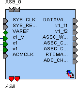
| Representation of an instance in your design. An instance is a component that has been added to your SmartDesign component. The name of the instance appears at the top and the name of the generic component at the bottom. The instance type is indicated by an icon inside the instance. There are specific icons for instances from SmartDesign, CoreConsole, HDL, and ViewDraw. The instance icon at left indicates an Microchip core. |
Icon | Description |
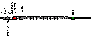
| Bus instance; you can click and drag the end of a bus instance to resize it; also, the bus instance will resize based on the number of instances that you connect to it. |
| Optional unconnected pin. Required pins are red. |
| Connected pin |
| Pin with default Tie Off |
| Pin tied low |
| Pin tied high |
| Pin inverted |
| Pin marked as unused |
| Pin tied to constant |
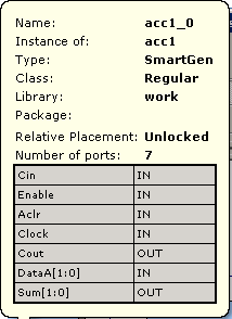
| Instance details. If there are less than twenty ports, they are listed in the details. |
Icon | Description |
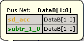
| Bus Net details. |
| Master bus interface icon. A master is a bus interface that initiates a transaction on a bus interface net. An unconnected master BIF with REQUIRED connection is red (shown at left). A master BIF with unconnected OPTIONAL connection is gray. |
| Master BIF details, showing name, role, and state. The Pin Map shows the Formal name of the pin assigned by the component (in this example, RCCLKOUT) and the Actual, or representative name assigned by the user (CLKOUT). |
| Slave BIF (shown at left). Unconnected slave icons with REQUIRED connections are red. Unconnected slave icons with OPTIONAL connections are gray. |
| Slave BIF details, showing name, role, and state. The Pin Map shows the Formal name of the pin assigned by the component (in this example, RCCLKOUT) and the Actual, or representative name assigned by the user (CLKA). |
| Master-slave bus interface connection |
| Master-slave bus interface connection details. |
Icon | Description |
| Groups of pins in an instance. Fully connected groups are solid green. Partially connected groups are gray with a green outline. Unconnected groups (no connections) are gray with a black outline. |
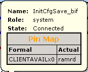
| A system BIF is the bus interface that does not have a simple input/output relationship on both master/slave. This could include signals that only drive the master interface, or only drive the slave interface, or drive both the master and slave interfaces. |
| System BIF details, showing name, role, and state. The Pin Map shows the Formal name of the pin assigned by the component (in this example, CLIENTAVAILx0), and the Actual name assigned by the user (in this example: ramrd). |
Icon | Description |
Icon | Description |
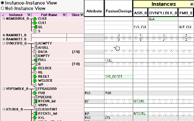
| Display panel (default Instance-Instance view). Note the +/- next to the instances to expand and contract the lists. You can click and drag an edge to resize the columns in the Display panel. Click and drag the column headings (Instance, Port Name, Slice, etc.) to change the order of the columns. Right-click the column headings to modify the fields (show/hide Instance, Port, etc.) |
| |
| Output icon (Port field). Shows that the port is a connected (green) output (letter O). |
| Input icon (Port field). Shows that the port is a connected (green) input (letter I). |
| INOUT icon (Port field). Shows that the port is a connected INOUT port. Unconnected INOUT ports are white. |
| Disconnected (white) output icon |
| Disconnected input icon |
| Master icon, connected |
| Master icon, unconnected |
| Slave icon, connected |
| Slave icon, unconnected |
Icon | Description |
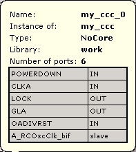
| Display panel instance details. Name is the name of your component; the default name for components is <instance>_0. Instance of specifies the component that was used to create the instance. Type shows the origin of the component, such as Design Block if the component was created from the the Catalog, or IP if the core was created by CoreConsole. Library is the library location of the core. |
Icon | Description |
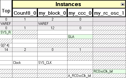
| Connection panel (Instance-Instance view). This default view of this panel shows your top level, all instances, and their corresponding connections to instances in the Display panel. Use the filter button identical instances are grayed out. Also, inputs may only be connected to outputs, outputs only connected to inputs. INOUT ports may be connected to inputs or outputs. |
Icon | Description |
| White, empty cells indicate that a connection is possible, but not active. |
| White cells with text indicate that the cell is connected and a non-driver. |
| Light green cells indicate that the cell is connected and is a driver. |
| Gray cells are read-only and indicate that the connection is exclusively reserved for pads. |
| Blue dotted cells indicate that there are multiple connections at that intersection - the number in the cell shows how many connections there are; click the cell to view the connections. |
| Black dotted cells indicate that multiple connections are possible - the number in the cell indicates how many connections are available; expand the instance in the Display panel to show more connections. |
| Diagonal hatch cells indicate no legal connections are possible |
Icon | Description |
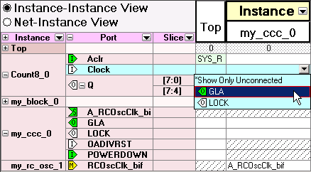
| List of ports available to connect. The intersection of an instance in the Display panel and an instance in the Connection panel enables a drop-down menu. Select the pin you want to use to connect the two instances from the drop-down menu. Icons in the drop-down menu represent whether the connection is a connected input, output, master, or slave. See the Display panel icon list for more information. |
Icon | Description |
| Schematic input icon |
| Schematic output icon |
| Schematic inout icon |
| Schematic input icon (multiple addresses) |
| Schematic connection icon |
| Schematic connection icon (multiple connections) |
Icon | Description |
| Schematic inverter icon; hover your mouse over the inverter symbol in the schematic view for more information on the state of your inverter. An inverter symbol does not necessarily indicate that all your pins are inverted. |
Using the HDL Editor
The HDL Editor is a text editor designed for editing HDL source files. In addition to regular editing features, the editor provides a syntax checker.
You can have multiple files open at one time in the HDL Editor workspace. Click the tabs to move between files.
CoreConsole only: If you use the template created by CoreConsole to instantiate the top level of the CoreConsole project, you must create a new HDL source file and copy the content of the template. If you do not, Libero IDE overwrites the file if you re-import a CoreConsole project.