9.4.3 Chain Programming Tutorial
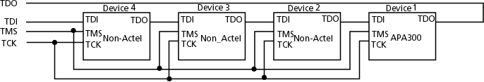
This tutorial demonstrates how to program an APA300 device that is part of a heterogeneous JTAG chain. The example uses one APA300 device and three non‑Microchip devices, configured as shown in the figure.
Note: This tutorial is performed in Advanced Mode. You can switch to Advanced Mode from the
Preferences dialog box.
To create a new project:
- Click the New Project button in FlashPro®.
- In the New Project dialog box, type Tutorial in the Project Name field.
- Select the Chain
option in the Programming Mode.
Figure 9-29. New Project Dialog Box 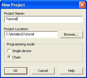
- If necessary, change the default location of your project in the Project Location field.
- Click OK.
Figure 9-30. FlashPro Main GUI 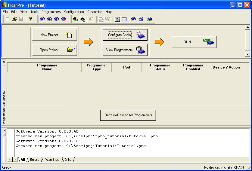 Note: The Programmer List window updates to display the connected programmer information.
 - From the Menu bar,
click (or select the programmer in the Programmer List
Window, right-click and choose Scan
Chain).
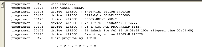
Scan Chain shows how the devices are ordered in the chain in the Log window (see figure below). In this example, APA300 is the first device and will be programmed first in the chain since it is connected directly to TDO.
Figure 9-31. Log Window Scan Chain Order 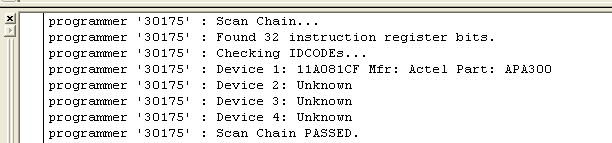
- From the Chain Configuration
window, click either ;
 or
or  buttons to add devices to the chain. In this example, click the Add Actel
Device button because the APA300 is the first device in the chain.
buttons to add devices to the chain. In this example, click the Add Actel
Device button because the APA300 is the first device in the chain.Figure 9-32. Add Actel Device 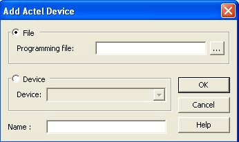
- Select the File radio button and click the Browse button to find your programming file.
- Select the Device radio button, then choose the APA300 device from the Device drop-down.
- In the STAPL File
field, load the APA300.stp file by using the Browse button
 to locate the file.
 - In the Name field, keep APA300 as the default name.
- The APA300 device is added to the
Chain Configuration window.
Figure 9-33. Chain Configuration Window: Device One 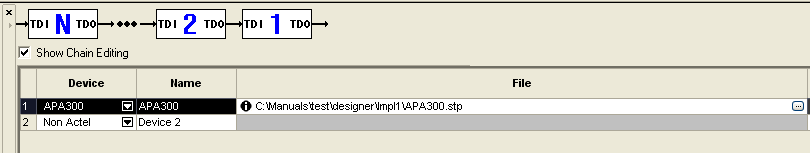
- Click the Add Non-Actel Device button to add the non-Actel device.
You can load the BSDL file or enter the IR length and Max TCK Frequency of the device. In
this tutorial, you will enter the IR length and Max TCK frequency for this device.
Figure 9-34. Add Non-Actel Device Window 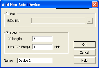
- For this device, enter 8 in the IR length field and keep the Max TCK freq default to 1MHz.
- Name the device, Device 2 and click OK. The second device now
appears in the Chain Configuration window. Repeat this step Device 3 and Device 4.
Figure 9-35. Chain Configuration Window: Device Two
- Check the Enable Device box for the APA300 device.
- After you add all the devices in the chain, the Chain Configuration
Window should look like the following figure.
Figure 9-36. Chain Configuration Window: All Devices in the Chain 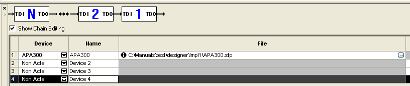
- After you have added all of the devices to the chain in the correct order, click the Run button to program the chain.
- When programming is complete, the results
are listed in the Log window.
Figure 9-37. Programmer List Window: Programming Complete